Do you have a question about the Gree GWH18KG-K3DNA5G and is the answer not in the manual?
| Brand | Gree |
|---|---|
| Model | GWH18KG-K3DNA5G |
| Category | Air Conditioner |
| Language | English |
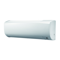
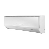
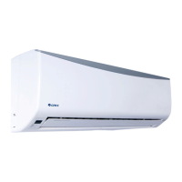
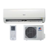
Overview of indoor units, outdoor units, and remote controllers with visuals.
Details technical parameters for indoor and outdoor units, including electrical, physical, and performance data.
Displays dimensional drawings and measurements for the indoor unit.
Displays dimensional drawings and measurements for the outdoor unit.
Illustrates the refrigerant flow and main components of the system.
Shows electrical connections for the indoor unit and includes a symbol key.
Illustrates top/bottom views of indoor/outdoor unit PCBs with numbered components.
Explains the buttons and icons on the remote controller for operating the air conditioner.
Details the operating modes (Cooling, Dry, Fan, Heating, Auto) and unit functions.
Provides important safety precautions and instructions for installation and maintenance.
Illustrates required clearances and dimensions for indoor/outdoor unit installation.
Lists the necessary parts for installation and maintenance.
Guides on choosing suitable locations for indoor/outdoor unit installation to avoid malfunctions.
Outlines electrical safety precautions, grounding, and wiring requirements for installation.
Details the process for selecting location and installing the indoor unit, including wall mounting.
Describes steps for installing the outdoor unit, including fixing support and connecting pipes.
Explains vacuum pumping and checking for refrigerant leaks after installation.
Provides checklist for verifying installation and performing test operations.
Explains how malfunctions are displayed on unit/remote, including an error code list.
Provides flowcharts for diagnosing and troubleshooting specific malfunctions like temperature sensor issues.
Offers solutions for common issues like unit not starting, poor cooling/heating, and louver problems.
Shows exploded view of indoor unit and detailed parts list with codes.
Displays exploded view of outdoor unit and its corresponding parts list with codes.
Step-by-step instructions with diagrams for disassembling the indoor unit, including filters and panels.
Step-by-step instructions with diagrams for disassembling the outdoor unit, including panels, fans, and valves.