26
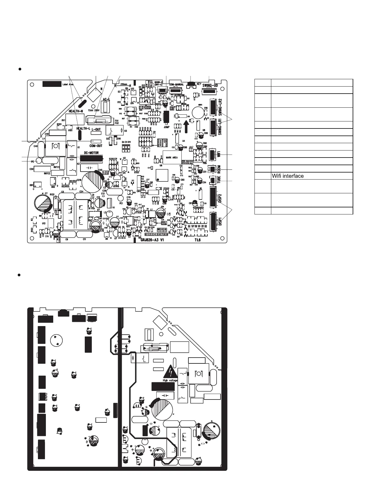
5.2 PCB Printed Diagram
Indoor Unit
Bottom View
1Grounding wire
2 DC motor needle stand
3
Communication terminal for
outdoor unit
4
Interface of health function(only
for the mode with this function)
5Interface of neutral wire
6Fuse
7Interface of live wire
8 Needle stand for jumper cap
9Auto button
10 up&down swing interface
11 Left&right swing interface
12
13
Interface of ambient temperature
sensor
14
Interface of tube temperature
sensor
15 Display interface
1
2
3
4567 8910
11
12
13
14
15
 Loading...