5
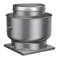
Upblast Centrifugal Roof Exhaust Fans
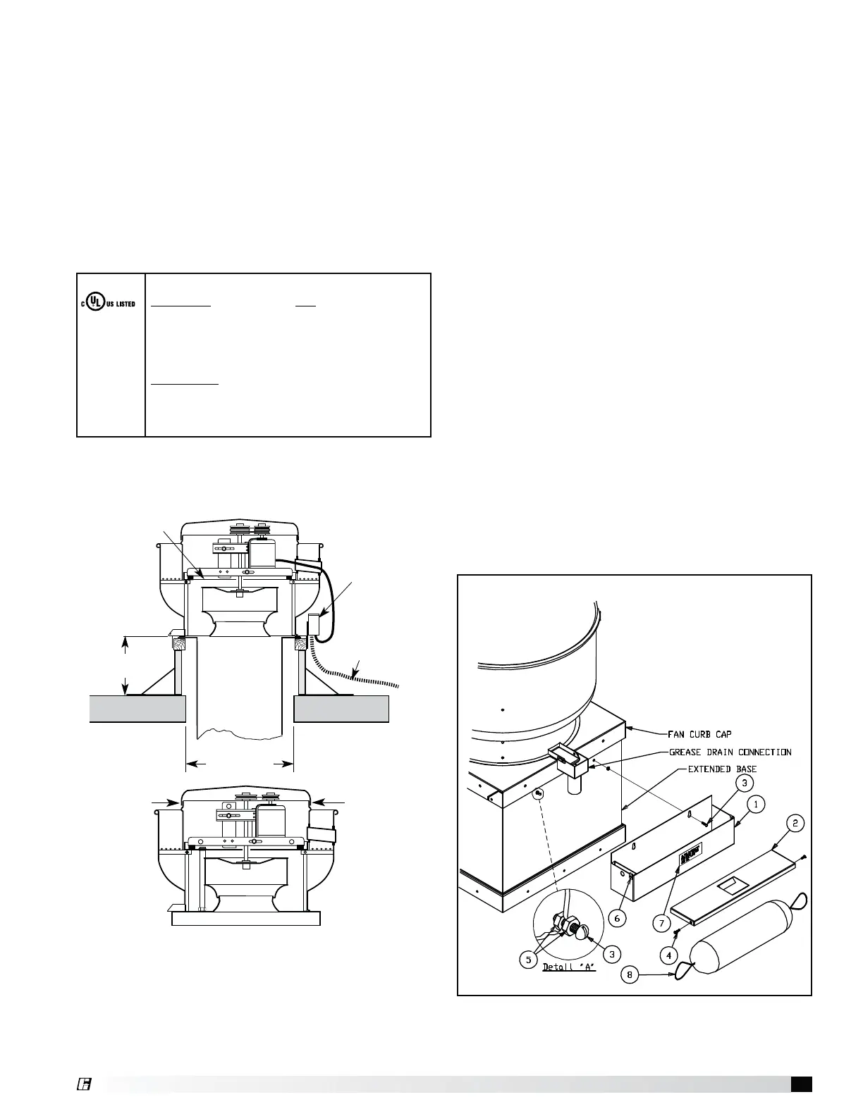
Grease Trap
A grease trap is an aluminum trap designed to collect
grease residue to avoid drainage onto roof surface. It
contains a built-in water separating baffle.
Instructions
1. Apply cover to grease trap. Install clip nuts to trap
over holes provided. Attach cover with two no.
10 - 24 x 1/2 fasteners.
2. Position the container under the grease drain so
the drain spout enters the cover approximately
1-1/2 to 2in. (38 to 51 mm).
3. Locate and mark the container mounting holes on
the extended base or roof curb.
4. Drill 3/16 in. (5 mm) diameter holes in marked
loations.
5. Apply container with no. 10 - 24 x 3/4 fasteners.
See Detail “A” in figure 6. If extended base is vented
type, allow space between screw head and container
for vent projections.
6. For most climates, fill container with water (at
installation and after each cleaning) until it flows out
the drain hole. The unit is now ready for use.
Maintenance
Regular inspection of grease trap is recommended.
Depending on the amount of grease discharged through
the fan, the grease trap should be changed accordingly
to ensure proper operation.
Grease Trap Installation
Parts List
1 - Grease Trap
2 - Grease Trap Cover
3 - No. 10 24 x 3/4 Slot RD HD SS MS
4 - No. 10 24 x 1/2 Slot RD HD SS MS
5 - No. 10 24 Hex SS Nut
6 - No. 10 24 Clip Nut
7 - Instruction Label
8 - Optional Grease Absorber
Fig. 6
Factory
Installed
Heat Baffle
8 in. (203 mm)
minimum
Recommended
Roof Opening
NEMA-3R
Disconnect
factory wired
from motor to
disconnect
through the
breather tube
Liquid Tight
Flexible Conduit
by Others
Roof Deck
Recommended Emergency Smoke
Control Installation
Electric Connection
Emergency Smoke Control
The motor’s amperage and voltage rating must be
checked for compatibility to the supply voltage prior to
final electrical connection. Also, the motor itself cannot
have thermal overload.
For emergency smoke removal application, the electrical
supply must enter the motor compartment through the
breather tube. Disconnect must be mounted outside the
fans motor compartment. Consult local code authorities
for your specific requirements. Shown below is the UL
Listed label that the fan will bear.
For belt drive units in emergency smoke removal
installations, the electrical supply must be kept out of
the airstream. They may also require an isolated power
supply so that if power is cut to the building in the event
of a fire, the fan will continue to operate. Check the
local and national electrical codes for emergency smoke
removal fans.
Listed
Power
Ventilator
For
Smoke
Contol
Systems
76Y9
-- IMPORTANT --
ELECTRICAL -- If fan motor is NOT thermally protected,
remote overload protection must be installed having
adequate rating as to voltage, frequency, horsepower,
and full load current per phase. Where connected to a
circuit protected by fuses, use time delay fuses. For supply
connection, use wires rated for at least 90
°
C (194°F).
INSTALLATION -- When connecting electrical power
to this fan, do not restrict motor movement. Motor must
have sufficient movement for possible future belt or wheel
adjustment.
454975
Screw
Screw
®