EasyManua.ls Logo

Greenheck HOA - User Manual

Greenheck HOA
7 pages
Print Icon
To Next Page IconTo Next Page
Loading...
GREENHECK

in 



Installation, Operation and Maintenance Manual
 
   
 

General Information



WARNING
 





 





HOA Controller Features


 
 







Table of Contents


 


 
 
 


 

 1
Question and Answer IconNeed help?

Do you have a question about the Greenheck HOA and is the answer not in the manual?

Overview

The Greenheck HOA Controller is a 24Vac/dc HOA Controller designed for use with fans, providing comprehensive control and monitoring capabilities. This device is intended for installation and maintenance by qualified personnel following all local electrical and safety codes, including the National Electrical Code (NEC) and National Fire Protection Agency (NFPA), as well as the Canadian Electrical Code (CEC) and ULC-S650.

Function Description

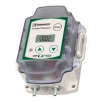
The HOA Controller serves as a central control unit for fan operation, offering both local and remote control options. It features an OLED display with a user-friendly keypad interface for easy configuration and status monitoring. The controller supports various operating modes, including Hand/Off/Auto (HOA), Auto Local, Auto Remote, and Fireman's Override, allowing for flexible integration into building management systems.

Key functions include:

  • Motor Control: The controller manages the operation of a fan motor, supporting both 24Vac/dc and 120-277Vac, 50/60Hz power inputs for the motor. It provides outputs for motor control based on selected operating modes and input signals.
  • Voltage Presence Detection: The device monitors the presence of voltage, indicating operational status.
  • Run Status Relay Output: A dedicated relay output provides a signal indicating the fan's run status, which can be integrated into external monitoring systems.
  • Dry Input: The controller includes a dry input for external contact closure, enabling remote control or interlocks.
  • 0-10V Input/Output: It supports 0-10V input for remote control signals (e.g., speed control) and provides a 0-10V output for auxiliary control.
  • Fireman's Override: A critical safety feature, the Fireman's Override allows for emergency operation of the fan, bypassing normal control logic. This mode is typically activated by a 12V-115V input signal.
  • Damper Control: The controller can manage damper operation, with outputs for both normally open (NO) and normally closed (NC) damper configurations.

Important Technical Specifications

  • Input Power: 24Vac/dc.
  • Temperature Range: -4° to 140°F (-20° to 60°C).
  • Fireman's Voltage Input: 12Vac – 115Vac.
  • Voltage Input Auto Local/Auto Remote: 12Vac – 115Vac.
  • Dry Input Auto Local/Auto Remote: Provides contact closure between Auto and C.
  • Run Status: Closes when ≥ 2.0V motor speed.
  • Auxiliary Contact: The N.O./N.C. changes state at 1.89Vdc. Contact rated for 10A at 24-240Vac, 5A at 30Vdc.
  • Remote Dial or Control Input: 0 - 10V input. +24V available for source powering Remote Dial or Sensor.
  • Motor Power: 100-277Vac, 50/60Hz.
  • Display: OLED with user-friendly keypad interface.
  • Dimensions: Approximately 5.77" (H) x 4.14" (W) x 1.92" (D) for the main unit, with mounting holes at 0.186" diameter, 4-places.

Usage Features

  • Simple Installation & Setup: The controller is designed for straightforward installation and initial setup, with clear wiring diagrams and specifications provided in the manual.
  • User-Friendly Interface: The OLED display and keypad allow for intuitive navigation and configuration of settings, including operating modes, speed control, and Fireman's Override setpoints.
  • Multiple Operating Modes:
    • Press Mode V1.00: The initial display upon power-up.
    • HAND Mode: Activates manual motor operation. Users can adjust motor speed using the up/down arrows.
    • OFF Mode: Disables the motor.
    • AUTO LOCAL Mode: Enables automatic operation based on local inputs (e.g., contact closure or 0-10V input).
    • AUTO REMOTE Mode: Enables automatic operation based on remote inputs (e.g., 0-10V signal from a control input terminal block).
    • FIREMAN Mode: Activates the Fireman's Override, forcing the fan to operate at a predefined setpoint. The Green Voltage Present LED will flash in this mode.
  • Software Version Display: Users can view the current software version installed on the controller.
  • Factory Reset: A function to revert all settings to their factory defaults.
  • Troubleshooting Guide: The manual includes a comprehensive troubleshooting guide to assist in diagnosing and resolving common issues related to power, display, motor operation, and run status.

Maintenance Features

  • Regular Inspections: Periodic inspections are recommended to ensure the controller and associated wiring are in good condition. This includes checking for loose connections, damaged insulation, or signs of overheating.
  • Software Updates: While not explicitly detailed as a user-accessible feature, the ability to display the software version suggests that updates may be available or performed by qualified technicians.
  • Fault Diagnosis: The troubleshooting guide provides specific symptoms, potential issues, and recommended fixes, aiding in efficient maintenance and repair. For example, if the motor does not turn ON in Hand Mode, potential issues include incorrect wiring, no motor input power, or a faulty motor, with corresponding fixes such as validating wiring, input power, and motor functionality.
  • Component Replacement: In cases of component failure, the manual emphasizes contacting a local representative or manufacturer for replacement parts, ensuring compatibility and proper functioning.
  • Unpacking and Inspection: Upon receiving the product, it is crucial to inspect all items for damage and verify the contents against the packing list. Any damage or discrepancies should be reported immediately.

Storage

Controls should be protected against damage during shipment and storage. If the control cannot be installed and operated immediately, precautions are needed to prevent deterioration of the control during storage. The user assumes responsibility of the control and accessories while in storage. The manufacturer will not be responsible for damage during storage. These suggestions provide solely as a convenience to the user.

Indoor Environment

The ideal environment for the storage of controls and accessories is indoors, above grade, in a low humidity atmosphere that is sealed to prevent the entry of blowing dust, rain or snow. Care must be taken to protect controls and accessories from dirt, moisture, and extreme temperature during storage. Improper storage which results in damage to the product will void the warranty.

Unpacking

Verify that all of the required parts and the correct quantity of each item have been received. If any items are missing, report shortages to your local representative to arrange for obtaining missing parts. Sometimes it is not possible that all items for the job be shipped together due to availability of transportation and truck space. Confirmation of shipment(s) must be limited to only items on the bill of lading.

Our Commitment

As a result of our commitment to continuous improvement, Greenheck reserves the right to change specifications without notice. Product warranties can be found online at Greenheck.com, either on the specific product page or in the literature section of the website.

Greenheck HOA Specifications

General IconGeneral
BrandGreenheck
ModelHOA
CategoryController
LanguageEnglish

Related product manuals