Do you have a question about the Greenheck MS-1P and is the answer not in the manual?
Defines DANGER, WARNING, and CAUTION signal words used in the manual for hazard communication.
Provides essential safety instructions for installation, operation, and servicing, emphasizing lockout/tagout procedures and qualified personnel.
Details how to mount the starter on a junction box, including cover removal and screw usage.
Guides on connecting main power input/output wires using appropriate connectors and copper conductors.
Specifies requirements for automation system control wiring, including conduit and terminal torque.
Explains how to set the overload protection by adjusting the dial to match the motor's FLA.
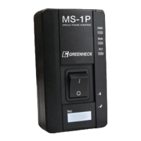
Describes Manual (HAND) and Automatic (AUTO) modes for motor control.
Details the meaning of PWR, RUN, and FLT LEDs for status monitoring.
Describes how to use the lockout feature by sliding the cover to access the grasp and insert a padlock.
Lists key product ratings including Horsepower, Short Circuit Protection, Interrupt Current, Max Current, and Overload.
States Greenheck's commitment to improvement, the right to change specifications, and warranty information location.
The Greenheck Motor Starter MS-1P is a single-phase starter designed for controlling and protecting single-phase motors. It functions as a motor disconnect, manual motor starter, and provides overload protection for loads up to 16 amps. The device is suitable for use on circuits capable of delivering not more than 5kA RMS Symmetrical Amperes at 240 volts maximum.
The MS-1P motor starter offers three primary operational modes: RESET, MANUAL (HAND), and AUTOMATIC (AUTO). In MANUAL mode, the starter acts as a motor disconnect or manual motor starter, engaging the motor when the main power switch is set to the ON (I) position. In AUTOMATIC mode, motor operation (ON or OFF) is determined by a signal received via the terminal inputs located on the rear of the unit. The RESET mode is used to clear a fault condition after a 180-second cool-down period has elapsed, requiring the 3-position switch to be held in RESET for a minimum of 5 seconds.
The MS-1P features an overload adjustment dial, accessible with a flathead screwdriver, to set the desired amperage for proper overload protection, ensuring it matches the nameplate Full Load Amperage (FLA) of the motor. The starter is not rated to protect loads exceeding 16 amps.
LED status indicators provide visual feedback on the unit's operational state:
For security and to prevent unauthorized access or tampering, the starter includes lockout options. The lower cover slides upward to reveal a concealed locking grasp, allowing a standard padlock to be inserted. An optional padlocking attachment (not included) can be used if multiple padlocks are required.
Installation requires mounting the starter on a minimum 14 cu-in single-gang junction box using the provided 6-32 x 7/8-inch mounting screws. Access to mounting holes is gained by sliding the upper and lower covers to the open position. It is crucial to install the starter in UL Type 1 (NEMA-1) appropriate locations, ensuring a dry, protected environment free from flammable gases, dusts, or materials. Metal shavings or debris must not enter the enclosure during installation. Main power input and output wiring should use properly sized wire nuts with copper conductors rated at least 60°C, maintaining proper clearances to prevent electrical shorts. Automation system control wiring should be run in a separate conduit.
Maintenance and installation should only be performed by qualified, expert personnel. The manual emphasizes reading all instructions thoroughly and observing all safety information to prevent personal injury and property damage. Disconnecting and locking out all power before installing or servicing equipment is mandatory, as the equipment may start automatically and may require locking out multiple power sources. The unit should not be disassembled or repaired unless specifically described in the manual, to avoid electrical shock or fire hazards. Specifications and manual data are subject to change, and the factory should be consulted for additional information.
The device is designed for manual reset after an overload trip, requiring the user to slide the 3-position switch to RESET and hold it for a minimum of 5 seconds after the 180-second cool-down period. This ensures that the motor has had sufficient time to cool before attempting to restart.
| Brand | Greenheck |
|---|---|
| Model | MS-1P |
| Category | Controller |
| Language | English |