EasyManua.ls Logo

Greenheck IDHB - User Manual

Greenheck IDHB
12 pages
Print Icon
To Next Page IconTo Next Page
Loading...
These instructions apply to zero clearance installation of electric duct heaters within ducts. They are approved for
use with heat pumps, air conditioners, or other forced air systems and may be controlled by contactors, relays,
sequencers, or solid state devices.
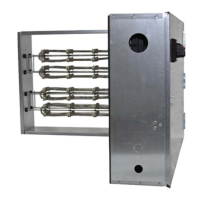
Greenheck duct heaters are pre-wired, factory tested, and furnished with integral controls.
Receiving and Handling
Upon receiving heater, check for both obvious and
hidden damage. Check all insulators for breakage and
inspect heater element wire(s) for any deformation
or damage that could cause a sort circuit to
ground. Make sure all fasteners are tight. Electrical
connections such as pressure terminals should be
checked for tightness. If damage is found, record all
necessary information on the bill of lading and file
a claim with the final carrier. Check to be sure that
all parts of the shipment, including accessories, are
accounted for.
Heaters must be kept dry and clean. Indoor storage
and protection from dirt, dust and the weather is
highly recommended. Do not store at temperatures in
excess of 100°F (38°C).
This manual is the property of the owner and is required for future maintenance. Please leave it with the owner when
the job is complete.
Safety Warning
Improper installation, adjustment, alteration, service
or maintenance can cause property damage, injury
or death. Read the installation, operating, and
maintenance instructions thoroughly before installing
or servicing this equipment.
Table of Contents
General Information . . . . . . . . . . . . . . . . . 1
Electrical Requirements. . . . . . . . . . . . . . . 2
Minimum Air Velocities . . . . . . . . . . . . . . 2-3
Installation. . . . . . . . . . . . . . . . . . . . .4-5
Insulated Duct Installation . . . . . . . . . . . . . 6
Installation Details with SSR Controllers . . . . . . 7
Troubleshooting Guide . . . . . . . . . . . . . . 8-9
“UL Listed (see complete marking on product)
ANSI/UL Standard 1996 (File E366239)
IDHB and IDHE series are intended for installation
in accordance with electric heaters requirements
established by:
National Fire Protection Association
NFPA Standards 90A and 90B
NFPA Standard 70
General Information
Refer to:
“Installation Supplement for Outdoor Heater
Applications (Document #484166) for additional
details.
®
Electric Duct Heaters 1
Document 478052
IDHB and IDHE
Duct Heaters
Installation, Operation and Maintenance Manual
Please read and save these instructions for future reference. Read carefully before attempting to assemble, install,
operate or maintain the product described. Protect yourself and others by observing all safety information. Failure
to comply with these instructions will result in voiding of the product warranty and may result in personal injury
and/or property damage.
Question and Answer IconNeed help?

Do you have a question about the Greenheck IDHB and is the answer not in the manual?

Overview

This document is an Installation, Operation, and Maintenance Manual for Greenheck IDHB and IDHE series electric duct heaters. These heaters are designed for zero-clearance installation within ducts and are approved for use with heat pumps, air conditioners, or other forced air systems. They can be controlled by contactors, relays, sequencers, or solid-state devices. Greenheck duct heaters are pre-wired, factory-tested, and furnished with integral controls.

Function Description:

The Greenheck IDHB and IDHE electric duct heaters provide supplemental heating within HVAC duct systems. They are designed to integrate seamlessly into existing forced air systems, offering a reliable heat source. The heaters are UL Listed under ANSI/UL Standard 1996 (File E366239) and comply with National Fire Protection Association (NFPA) Standards 90A, 90B, and 70 for electric heater requirements.

Important Technical Specifications:

  • Installation: Zero-clearance installation within ducts.
  • Airflow: Approved for use with heat pumps, air conditioners, or other forced air systems.
  • Control: Compatible with contactors, relays, sequencers, or solid-state devices. Pre-wired with integral controls.
  • Wiring: Requires 90°C (194°F) copper wire. Control wiring must be N.E.C. Class 1 unless otherwise specified.
  • Voltage/Phase: Must match the specifications on the heater nameplate label.
  • Minimum Air Velocity: Directly related to the inlet air temperature. Charts are provided for IDHB (Watts per Square Foot vs. Minimum Air Velocity) and IDHE (Inlet Air °F vs. CFM/KW Minimum and FPM Chart vs. KW/Ft²). For IDHE, the maximum inlet air temperature is 110°F, and the maximum heater KW is 30 KW per Square Foot of Duct Cross Section.
  • Duct Orientation: Can be installed in vertical sides of horizontal or vertical ducts, but never in the top or bottom of a horizontal duct. IDHB heaters are approved for up airflow only in vertical ducts. IDHE heaters are approved for both up and down airflow in vertical ducts. Approved for both airflow directions in horizontal ducts.
  • Clearances:
    • Minimum 4 feet from heat pumps, central air conditioners, air handlers, canvas duct connectors, duct transitions, air filters, and upstream from humidifiers.
    • Minimum 2 feet either side of an elbow or turn.
    • Minimum 24 inches from an elbow or turn (Figure 5).
    • Minimum 48 inches from heat pump/air conditioner (Figure 6), transition change (Figure 7), air handler (Figure 8), humidifier (Figure 9), and air filter (Figure 10).
  • SSR Control: For heaters equipped with SSRs (including SSR Vernier Control), they require a 0 to 10 VDC, 2 to 10 VDC, or 4 to 20 mA signal from the building's automation system or a local thermostat. Configuration dipswitches are used to set the common input type.

Usage Features:

  • Pre-wired and Factory Tested: Ensures ease of installation and reliable operation out of the box.
  • Integral Controls: Simplifies integration into HVAC systems.
  • Versatile Installation: Can be installed as slip-in or flange type heaters.
    • Slip-in Heater: Requires cutting an opening in the side of the duct, sliding the heater in, marking and drilling mounting holes, and securing with sheet metal screws.
    • Flange Heater: Inserted between two sections of flanged duct and bolted in place. Duct flange should be doubled for additional strength.
  • Control Cabinet Orientation:
    • IDHB: Control cabinet must be positioned as labeled on the unit.
    • IDHE: Control cabinet offset can be positioned in either direction.
  • Airflow Switch (when furnished): Ensures proper airflow. The pickup tube must be connected to the "LOW" port for negatively pressurized ducts and the opposite port for positively pressurized ducts. Note that an airflow switch only confirms airflow existence, not minimum air velocities or proper air distribution.
  • Duct Insulation Compatibility:
    • External Insulation: The external insulation must be removed from the area where the heater is mounted. Heater size is based on the duct size (no recess required).
    • Internal Insulation: For S-type ducts with internal insulation or ducts constructed from insulation board, the heater dimensions (H' and W') are adjusted based on insulation thickness (H' = Duct H - (Insulation Thickness x 2); W' = Duct W - Insulation Thickness). The internal insulation can be left in place with a recess or cut away from the mounting area.

Maintenance Features:

  • Troubleshooting Guide: Provides a comprehensive list of common installation and operational issues to prevent property damage, injury, or death. Key points include:
    • Never operate without airflow; always interlock with the fan.
    • Maintain minimum airflow velocity and even air distribution across the heater face.
    • Ensure incoming air is filtered and free from debris, combustible particles, and hazardous vapors.
    • Maintain proper clearances from other duct components and equipment.
    • Avoid installing standard heaters in ducts with internal obstructions; use heaters with recessed control boxes if necessary.
    • Never insulate the exterior of the control box; it must be accessible and ventilated.
    • Avoid installing near double blower outlets unless sufficient distance for even airflow is ensured.
    • Use only copper conductors for incoming wiring.
    • Do not install standard heaters outdoors without special protection from elements.
    • Do not bundle, tie, or wrap power wiring to prevent overheating.
    • Always use the specified voltage and phase listed on the nameplate.
  • Replacement Parts: Must be identical to the original components. Contact the factory for replacements.
  • Servicing: Disconnect all electrical power before servicing. Ensure all components are repositioned correctly and reconnected per the wiring diagram.
  • Documentation: The manual is the property of the owner and is required for future maintenance.

Greenheck IDHB Specifications

General IconGeneral
BrandGreenheck
ModelIDHB
CategoryHeater
LanguageEnglish