Electrical Requirements
Refer to the wiring diagram on inside of cover. Make
sure line and control voltage of system matches that
noted on wiring diagram.
Wire in accordance with N.E.C. and any existing local
codes. Check tightness of all factory and field electrical
connections. Make sure fan interlock is wired in if the
Duct Heater does not have an air flow switch.
Use 90°C (194°F) copper wire.
Control must be wired for N.E.C. Class 1 unless
otherwise specified.
When heater has integral transformer for control voltage
to thermostat, use thermostat with isolating contacts to
prevent interconnection of Class 2 outputs.
Disconnect all electrical power before servicing.
When servicing heater, make sure all components are
repositioned in the proper location and reconnected per
the wiring diagram.
Replacement parts must be identical to the original
components. Contact factory for replacement parts.
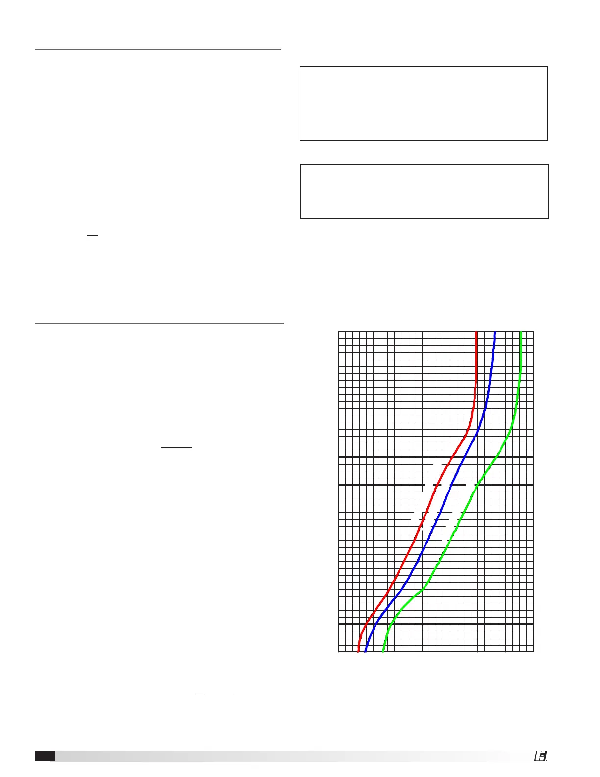
Minimum Air Velocities
The minimum uniform airflow in a duct heater is directly
related to the inlet air temperature. Consideration must
be given to both airflow across the heater and inlet air
temperature, (shown at right).
1. To calculate the watts per sq. ft. of duct area,
divide the total watts required by the duct area.
EXAMPLE: Duct Size = 2ft. x 3ft.
Total watts = 20,000
W/Sq. Ft. = 20,000 = 3333
6
2. If the air handler equipment is expressed in
fpm, then a direct cross reference can be made
by comparing the temperature of the air (as it
enters the Duct Heater) to the kW rating on the
chart of rated velocity.
a. Draw a line horizontally from the Watts/Sq. Ft.
required to the inlet air temperature being used.
b. From this point of intersection on the Inlet Air
Curve, draw a line down vertically to establish
the air velocity.
c. The velocity should never be lower than the
velocity as determined from the chart. In cases
where this is not true, the velocity must be
increased or the kW required must be reduced.
3. In cases where the air handling equipment is
expressed in CFM, convert to FPM by dividing
the CFM by the duct area.
EXAMPLE: FPM = CFM
Duct Area
1,400
4,000
6,000
8,000
10,000
12,000
14,000
16,000
18,000
20,000
WATTS PER SQUARE FOOT, DUCT AREA
22,000
Minimum Air Velocity (fpm)
2,000
1,2001,000800600400200
BELOW 78°F INLET AIR
78° TO 90°F INLET AIR
91° TO 110°F INLET AIR
Note: Minimum airflow must be maintained at any
point over the face of the heater. The velocity of air
should NEVER be lower than the specified minimum.
In cases where this is not true the KW must be
reduced or the velocity of air increased.
Note: Observe at least one complete heating cycle to
insure that cycling of the safety limit controls does not
occur before leaving the installation.
IDHB: Minimum Air Velocity
Electric Duct Heaters2
 Loading...