Model IG / IGX Make-Up Air 11
®
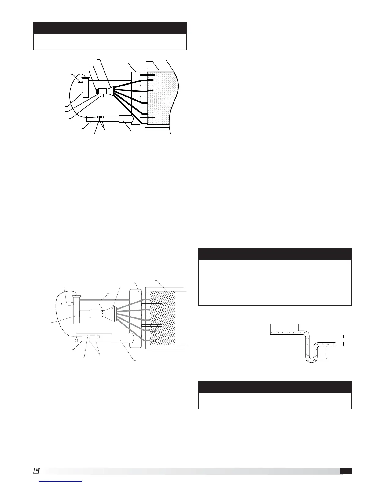
Installation with Hot Gas Bypass
NOTE
If a hot gas bypass kit was provided by others, refer to
the manufacturer’s instructions.
3. Install Suction Line
Install suction line(s) from the compressor to the suction
connection(s) which are stubbed through the side of the
cabinet.
4. Install the Liquid Line and Thermal
Expansion Valve (TEV) (by others)
Liquid line openings vary by coil size and circuiting and
are field-supplied. Follow the TEV recommendations
for installation to avoid damaging the valve. If the valve
is externally equalized, use a tubing cutter to cut off
the plugged end of the factory-installed equalizer line.
Use a de-burring tool to remove any loose metal from
the equalizer line and attach it to the TEV. If the valve is
internally equalized, the factory-installed equalizer line
can be left as-is.
General Installation
Expansion
alve (by others)
Liquid Line
Thermal
Nozzle
Suction Header
Coil
Distributor
Equalizer Line
Suction Line
Remote Sensing Bulb
Straps
Suction Connection
NOTE
Failure to obtain a high vacuum indicates a great deal
of moisture or a small leak. Break the vacuum with
a charge of dry nitrogen or other suitable gas and
recheck for leaks within the system. If no leaks are
found, continue to pull a vacuum on the coil until an
acceptable reading is reached (500 microns).
IMPORTANT
All traps must be installed below the roof line or be
otherwise protected from freezing.
5. Mount the Remote Sensing Bulb
(by others)
The expansion valve’s remote sensing bulb should be
securely strapped to the horizontal run of the suction
line at the 3 or 9 o’clock position and shall be insulated.
6. Check Coil Piping for Leaks
Pressurize the coil to 100 psig with dry nitrogen or other
suitable gas. The coil should be left pressurized for a
minimum of 10 minutes. If the coil holds the pressure,
the hook-up can be considered leak-free. If the pressure
drops by 5 psig or less, re-pressurize the coil and
wait another 10 minutes. If the pressure drops again,
there is likely one or more small leaks which should
be located and repaired. Pressure losses greater than
5psig indicate a large leak that should be isolated and
repaired.
7. Evacuate and Charge the Coil
Use a vacuum pump to evacuate the coil and any
interconnecting piping that has been open to the
atmosphere. Measure the vacuum in the piping using a
micron gauge located as far from the pump as possible.
Evacuate the coil to 500 microns or less and then close
the valve between the pump and the system. If the
vacuum holds to 500 microns or less for one minute,
the system is ready to be charged or refrigerant in
another portion of the system can be opened to the coil.
A steady rise in microns would indicate that moisture
is still present and that the coil should be further
vacuumed until the moisture has been removed.
8. Install the Drain Line
Connect an
unobstructed drain line
to the drain pan. A
trap must be used to
overcome the internal
negative pressure in the
unit and allow the water
to drain while the unit is operating.
6 in. min.
6 in. min.
Drain
Trap
Coil
Suction Header
Distributor
Equalizer Line
Nozzle
Liquid Line
Thermal Expansion
Valve
Hot Gas By-Pass
Hot Gas Side Port
Suction Line
Remote Sensing Bulb
Straps
Suction Connection
 Loading...