Model IG / IGX Make-Up Air 3
®
Indirect Gas-Fired Unit Installations
Units are listed for installation in the United States and
Canada.
• Installation of gas-fired duct furnaces must conform
with local building codes. In the absence of local
codes, installation must conform to the National
Fuel Gas code, ANSI Z223.1 or in Canada, CAN/
CGA-B149 installation codes.
• All electrical wiring must be in accordance with the
regulation of the National Electrical Code, ANSI/
NFPA 70.
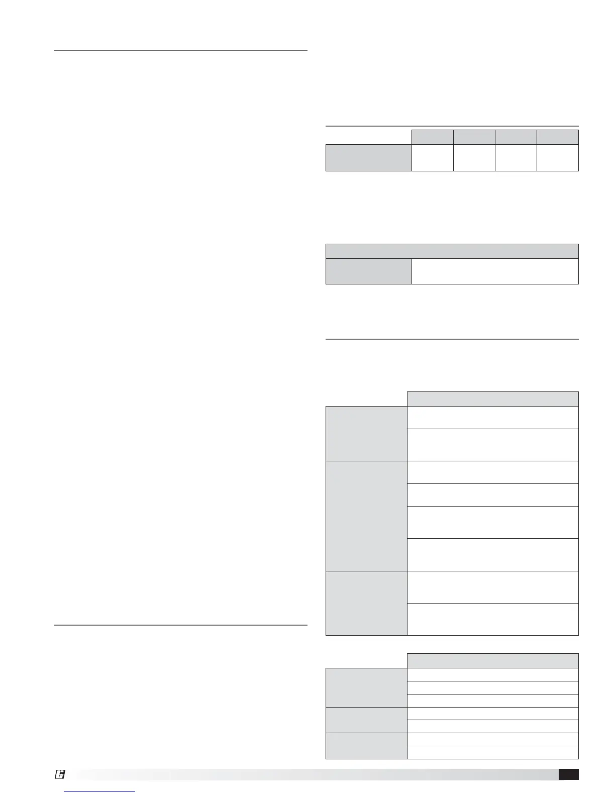
Clearance to Combustibles /
Service Clearances
Floor Top Sides Ends
Indirect Fired
Units*
0 inches
(0 mm)
0 inches
(0 mm)
0 inches
(0 mm)
0 inches
(0 mm)
Clearance to combustibles is defined as the minimum
distance required between the heater and adjacent
combustible surfaces to ensure the adjacent surface’s
temperature does not exceed 90° above the ambient
temperature.
*Reference venting guidelines for combustion blower clearances.
Recommended Minimum Service Clearances
Housing 32
and less
42 inches
(1067 mm)
on the
controls side of the unit
Clearances for component removal (such as evaporative
cooler media) should be 6 in. wider than the width of the
module itself.
Table of Contents
Installation
Indirect Gas-Fired Unit Installations .............3
Clearance to Combustibles/Service Clearances ....3
Additional IOMs for Reference ..................3
Indoor Unit .................................4
Unit Arrangement DB / HZ ................... 4-5
Roof Mounted Unit – Arrangement DBC ........ 5-6
Optional Evaporative Cooling Module ............7
Installation of Furnace Connections .............7
Electrical Wiring ........................... 7-8
Optional Evaporative Cooler Piping ........... 9-10
Optional Direct Expansion (DX) Coil Piping .... 10-11
Optional Chilled Water Coil Piping .............12
Optional Building Pressure Control .............12
Optional Dirty Filter Switch ...................13
Start-Up
Blower ................................ 13-14
Optional Economizer ..................... 15-16
Optional Evaporative Cooling .................17
Operation
Optional VAV Units ..........................18
Optional Recirculating Units ..................19
Sequence of Operation ......................20
Troubleshooting
Blower ...................................21
Motor Over Amps. . . . . . . . . . . . . . . . . . . . . . . . . . . 22
Insufficient / Too Much Airflow ................23
Excessive Noise / Vibration ...................24
Furnace ..................................24
Optional Evaporative Cooling .................25
Maintenance
Routine ................................ 26-27
Fall ................................... 28-29
Reference
Vent Connections ...........................30
Model IG – Single or 2 Stage ..................31
8:1 Staged ..............................32
4:1 Modulation ...........................33
Model IGX – Blower Control Center ............34
Start-Up Checklist ..........................35
Maintenance Log ................. Backcover
Our Commitment ................. Backcover
Additional IOMs for Reference
For complete furnace information reference the Indirect
Gas-Fired Heat Modules Installation, Operation and
Maintenance Manual. Available turndown control
options include:
Electronic Modulation
Single Furnace
Unit
4:1- uses modulating valve and furnace
controller
*High turndown uses a 4:1 modulating
valve with a proprietary manifold and
furnace controller
Two Furnace
Unit
8:1- uses one 4:1 modulating furnace with
furnace controller and one 2-stage furnace
4:1 - uses two 4:1 modulating furnaces
controlled in parallel
*High turndown furnaces in a series
configuration use one high turndown
furnace and one 2-stage furnace
*High turndown furnaces in a parallel
configuration use two high turndown
furnaces, controlled in parallel
Three Furnace
Unit
12:1 - uses one 4:1 modulating furnace,
one 2 stage furnace and one 1-stage
furnace
*High turndown uses one high turndown
furnace, one 2-stage furnace, and one
1-stage furnace
* High turndown furnace patent pending.
Staged
Single Furnace
Unit
8 stage
2 stage
1 stage
Two Furnace
Unit
4-stage uses two 2-stage furnaces
2-stage uses two single-stage furnaces
Three Furnace
Unit
6-stage uses three 2-stage furnaces
3-stage uses three 1-stage furnaces
• Unit is approved for installation downstream from
refrigeration units. In these conditions, condensate
could form in the duct furnace and provision must be
made to dispose of the condensate.
 Loading...