Model IG / IGX Make-Up Air8
®
1. Determine the Size of the Main Power
Lines
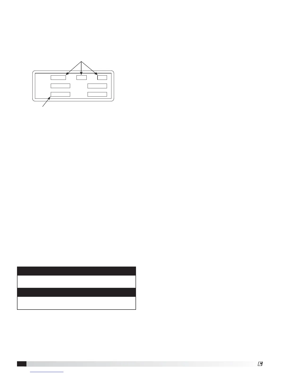
The unit’s nameplate states the voltage and the unit’s
total MCA. The main power lines to the unit should
be sized accordingly. The nameplate is located on the
outside of the unit on the control panel side.
2. Provide the Opening(s) for the
Electrical Connections
Electrical openings vary by unit size and arrangement
and are field-supplied.
3. Connect the Main Power
Connect the main power lines to the disconnect switch
and main grounding lug(s). Torque field connections to
20 in.-lbs.
4. Wire the Optional Convenience Outlet
The convenience outlet requires a separate 115V power
supply circuit. The circuit must include short circuit
protection which may need to be supplied by others.
5. Wire the Optional Accessories
Reference the ladder diagram on the inside of the
control center door for correct wiring of the following
accessories:
• Selectra Stat • Dirty Filter Indicator
• Room Override • Industrial Remote Panel
• Blower Switch • Kitchen Remote Panel
• Heat Switch • Economizer Activator
• Indicating Lights • Room Stat
SUP HP
MCA
EXH HP
MOP
VOLTS HZ PH
Unit’s Total MCA
Voltage, Hertz, Phase
Electrical Nameplate
NOTE
Wiring to the Selectra Stat or room override should be
in separate conduit or run with shielded cable.
NOTE
The Industrial Remote Panels use point-to-point
wiring to connect to the unit's main control center.
6. Wire the Evaporative Cooler (optional)
Reference the ladder diagram on the inside of the
control center door for correct wiring of the pump and
the optional water valves.
7. Install Economizer Sensors (optional)
All economizer options (EC) require an outdoor air
temperature or enthalpy sensor to be field-installed
inside of the weatherhood and field-wired to the
economizer. Reference unit specific ladder diagram from
proper terminals.
Economizer options EC-3 and EC-4 require a return air
temperature or enthalpy sensor to be field-installed in
the return air duct and field-wired to the economizer.
Reference unit specific ladder diagram from proper
terminals.
The sensors are provided by the factory and ship with
the unit.
8. Install Discharge Air Sensor
For units with 1:1, 2:1, 3:1, 6:1, 8:1, 16:1 and 24:1
staged turndown; or 4:1, 8:1, 12:1, and high turndown
electronic modulation, a discharge air sensor is used.
Upon installation, the sensor must be relocated from the
control center to the ductwork, at a minimum of three
duct diameters downstream of the heat exchanger.
9. Install DDC Interface (Optional)
Some units may use an external signal from a building
management system to control the dampers, discharge
air temperature, or other settings. Reference the unit
ladder diagram for the correct wiring.
 Loading...