Page 13
RNC 1.5 & RNC 2.0 Series
RNC 1.5 & RNC 2.0
Series
RNC 1.0 & RNC12 only
RNC 1.0 & RNC12 only
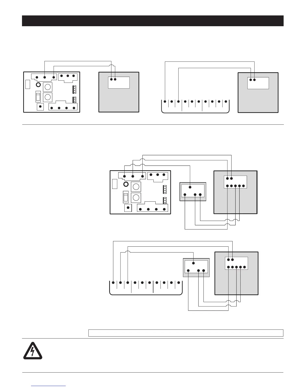
13. WIRING DIAGRAMS FOR FURNACE INTERLOCK SYSTEMS
STANDARD FORCED AIR INTERLOCKING WIRING
A relay is normally used when tying a ventilation system to the forced air distribution system. Our Duotrol System is equipped with an internal relay that will activate the
forced air system’ ventilator when there is a demand from the HRV /ERV. The Duotrol System will activate the INTERLOCK relay during the following modes: Continuous,
Override,Recirculation and Defrost. See wiring diagram.
ALTERNATE FORCED AIR INTERLOCKING WIRING
Some forced air system thermostat will activate the cooling system when tied using the «Standard forced air interlocking wiring». If you have identify this type of
thermostat you must proceed with the «Alternate Forced Air Wiring».
Locating the
Wiring Diagram
Note to installer: Wiring Diagram for
the entire line of HRV/ERV Models are
placed on the back of each Exhaust
motor bracket.
CAUTION: Thermostat that control A/C
system must use the Alternate Interlock
Wiring Diagram.
B
INTERLOCK
COMN.O.N.C.
RLY1
4321
D1
SW3
TIMER
REMOTE
W
B1
GR
GBR
MASTER
PROG
J2
–
+
CYWRG
B
INTERLOCK
COMN.O.N.C.
RLY1
4321
D1
SW3
TIMER
REMOTE
W
B1
GR
GBR
MASTER
PROG
J2
–
+
CYWRG
YWRG
CYWRG
COM NC NO BG
INTERLOCK TIMER
RB/B1W G
CONTROL
R
Terminal Barrier HRV/ERV Connection
COM NC NO BG
INTERLOCK TIMER
RB/B1W G
CONTROL
R
Terminal Barrier HRV/ERV Connection
Forced Air SystemForced Air SystemLow Voltage HRV/ERV Controller
Forced Air
System
Thermostat
Low Voltage HRV/ERV Controller
CYWRG
YWRG
Forced Air
System
Thermostat
B
INTERLOCK
COMN.O.N.C.
RLY1
4321
D1
SW3
TIMER
REMOTE
W
B1
GR
GBR
MASTER
PROG
J2
–
+
CYWRG
B
INTERLOCK
COMN.O.N.C.
RLY1
4321
D1
SW3
TIMER
REMOTE
W
B1
GR
GBR
MASTER
PROG
J2
–
+
CYWRG
YWRG
CYWRG
COM NC NO BG
INTERLOCK TIMER
RB/B1W G
CONTROL
R
Terminal Barrier HRV/ERV Connection
COM NC NO BG
INTERLOCK TIMER
RB/B1W G
CONTROL
R
Terminal Barrier HRV/ERV Connection
Forced Air SystemForced Air SystemLow Voltage HRV/ERV Controller
Forced Air
System
Thermostat
Low Voltage HRV/ERV Controller
CYWRG
YWRG
Forced Air
System
Thermostat
Standard forced air wiring diagram
*Before tying the HRV/ERV to a forced air system, always refer to system’s manual or manufacturer.
WARNING:
Always disconnect the unit prior to making any connections. Failure to disconnecting the power could result in electrical shock or can
damage the electronic boards, wall controls and/or unit.
CAUTION:
Minimum wire requirements is LVT18 CSA/UL 4 strain to insure proper connection.
 Loading...