EasyManua.ls Logo

GREER Company MicroGuard RCI 510 User Manual

GREER Company MicroGuard RCI 510
56 pages
To Next Page IconTo Next Page
Page #1 background imageLoading...
Page #1 background image
MicroGuard®
RCI 510
Rated Capacity Indicator System
Troubleshooting Manual

Table of Contents

Question and Answer IconNeed help?

Do you have a question about the GREER Company MicroGuard RCI 510 and is the answer not in the manual?

GREER Company MicroGuard RCI 510 Specifications

General IconGeneral
BrandGREER Company
ModelMicroGuard RCI 510
CategoryIndustrial Equipment
LanguageEnglish

Summary

Introduction

Where to go For Help

1.1 Overview & Preparation

SYSTEM SCHEMATIC OVERVIEW

Diagram illustrating the system's architecture and component connections.

2.1 SYSTEM SELF-TEST

THE DISPLAY CONSOLE

Details visual and auditory feedback during the self-test sequence.

2.2 DISPLAY CONSOLE PROBLEMS

2.3 FAULT REPORTING AND FAULT CODES

2.3.1 GROUP "A" FAULT CODES

2.3.2 GROUP "B" FAULT CODES

2.3.3 GROUP "C" FAULT CODES

2.3.4 GROUP "D" FAULT CODES

2.4 "NO FAULT CODE" PROBLEMS

2.4.1 ANTI TWO-BLOCK ALARM (A2B)

Guides fault diagnosis for Anti Two-Block alarm issues.

2.4.2 DISPLAYED LOAD OR RADIUS ERRORS

CHECK BOOM EXTENSION

Steps to verify boom extension accuracy and troubleshoot errors.

CHECK MAIN BOOM RADIUS

Procedures to check and calibrate main boom radius measurements.

CHECK BOOM ANGLE

CHECK PRESSURE SENSORS

PRESSURE MONITOR

Illustrates the pressure monitor display and expected values.

3.1 COMPUTER UNIT OVERVIEW

THE COMPUTER UNIT

Identifies the computer unit and its role in the system.

3.2 COMPUTER UNIT LAYOUT

3.3 INTERNAL STATUS INDICATORS

3.4 THE COMM INDICATOR

3.5 COMPUTER UNIT REPLACEABLE PART

3.5.1 FUNCTION KICKOUT FUSE (FUS1)

Details the function and replacement of the FUS1 fuse.

3.6 PRESSURE SENSORS

CHECKING PRESSURE SENSORS

Provides procedures for checking the pressure sensor readings.

PRESSURE MONITOR

Illustrates the pressure monitor display and expected values.

3.7 REPLACING THE COMPUTER UNIT

COMPUTER REMOVAL

Detailed instructions for safely removing the computer unit.

COMPUTER INSTALLATION

Step-by-step guide for installing the computer unit.

POWER UP AND CALIBRATION

Procedures for powering up and calibrating the unit after installation.

4.1 DISPLAY CONSOLE OVERVIEW

OPERATOR'S DISPLAY CONSOLE

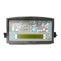
Illustrates the main display console and its layout.

4.3 CHECKING THE DISPLAY CONSOLE

4.3.1 READING THE LCD

Tips for optimizing display readability and addressing contrast issues.

4.3.2 UNRESPONSIVE BUTTONS

4.3.3 CONNECTORS

4.3.4 HORN

4.3.5 MOISTURE

4.4 REPLACING THE DISPLAY CONSOLE

5.1 REMOTE BAR GRAPH OVERVIEW

5.2 CHECKING THE REMOTE BAR GRAPH

5.2.1 LAMPS

Explains the operation and troubleshooting of the remote bar graph's LEDs.

5.2.2 BRIGHTNESS CONTROL

Details how to adjust and use the brightness control feature.

5.2.3 CABLE AND CONNECTOR

5.2.4 MOISTURE

5.3 REMOTE BAR GRAPH REPLACEMENT

6.0 ENTERING THE CALIBRATION MODE

6.1 EXTENSION REEL OVERVIEW

EXTENSION REEL CUT-AWAY DRAWING

Diagram showing the internal components of the extension reel assembly.

6.2 CHECKING THE REEL-OFF CABLE LAYERING

EXTENSION REEL VIEWED FROM ABOVE

Diagram illustrating the correct cable layering on the extension reel.

6.3 CHECKING THE EXTENSION SENSOR DRIVE VOLTAGE

6.4 CHECKING THE BOOM EXTENSION SENSOR VOLTAGE

SENSOR BASEPLATE ASSEMBLY WIRING

Wiring diagram for the sensor baseplate assembly.

6.5 EXTENSION SENSOR SETUP

6.5.1 PHYSICAL ZERO

Steps to set the physical zero for the extension sensor potentiometer.

6.5.2 ZERO CALIBRATION

How to calibrate the zero setting of the extension sensor potentiometer.

6.5.3 SPAN CALIBRATION

6.6 CHECKING THE ANGLE SENSOR PENDULUM

SENSOR ASSEMBLY

Diagram of the sensor assembly, highlighting the pendulum.

6.7 CHECKING THE ANGLE SENSOR DRIVE VOLTAGE

6.8 CHECKING THE ANGLE SENSOR VOLTAGE

SENSOR BASEPLATE ASSEMBLY WIRING

Wiring diagram for the sensor baseplate assembly.

6.9 ANGLE SENSOR SETUP

6.9.1 PHYSICAL ZERO

Steps to set the physical zero for the angle sensor potentiometer.

6.9.2 ZERO CALIBRATION

How to calibrate the zero setting of the angle sensor potentiometer.

6.9.3 SPAN CALIBRATION

6.10 EXTENSION REEL REPLACEABLE PARTS

6.10.1 EXTENSION REEL-OFF CABLE

Details the extension reel-off cable and its function.

REEL-OFF CABLE CONNECTION ON THE EXTENSION REEL

Diagram showing the reel-off cable connection.

REMOVING THE EXTENSION REEL-OFF CABLE

INSTALLING THE EXTENSION REEL-OFF CABLE

6.10.2 SLIP-RING ASSEMBLY

SLIP-RING ASSEMBLY

Diagram illustrating the slip-ring assembly and its connections.

REMOVING THE SLIP-RING ASSEMBLY

INSTALLING THE SLIP-RING ASSEMBLY

6.10.3 SENSOR BASEPLATE ASSEMBLY

SENSOR ASSEMBLY TERMINAL BLOCK WIRING

Wiring details for the sensor assembly terminal block.

REMOVING THE SENSOR ASSEMBLY

INSTALLING THE SENSOR ASSEMBLY

6.10.4 SIGNAL CABLE ASSEMBLY

SIGNAL CABLE TERMINAL BLOCK WIRING

Wiring details for the signal cable terminal block.

INSTALLING THE SIGNAL CABLE

7.1 ANTI TWO-BLOCK FUNCTION OVERVIEW

7.2 CHECKING THE EXTENSION REEL-OFF CABLE

7.3 CHECKING THE ANTI TWO-BLOCK CIRCUIT

SECTION 8 - POWER, KICKOUT & BOOM MODE OUTPUTS

9.1 SWING SENSOR OVERVIEW

SWING SENSOR SCHEMATIC

Diagram illustrating the swing sensor and its connections.

9.2 CHECKING THE SWING SENSOR DRIVE VOLTAGE

9.3 CHECKING THE SWING SENSOR OUTPUT VOLTAGE

9.4 CHECKING THE SWING SENSOR RESISTANCE

9.5 SWING SENSOR SETUP AND CHECKS

9.5.1 CHECKING AND SETTING ZERO

How to check and set the zero angle for the swing sensor.

9.5.2 CHECKING AND SETTING DIRECTION

How to check and set the direction for the swing sensor.