Operation manual SP 9 - Compact
CHAPTER III – DESCRIPTION OF PLOUGH – Page 8
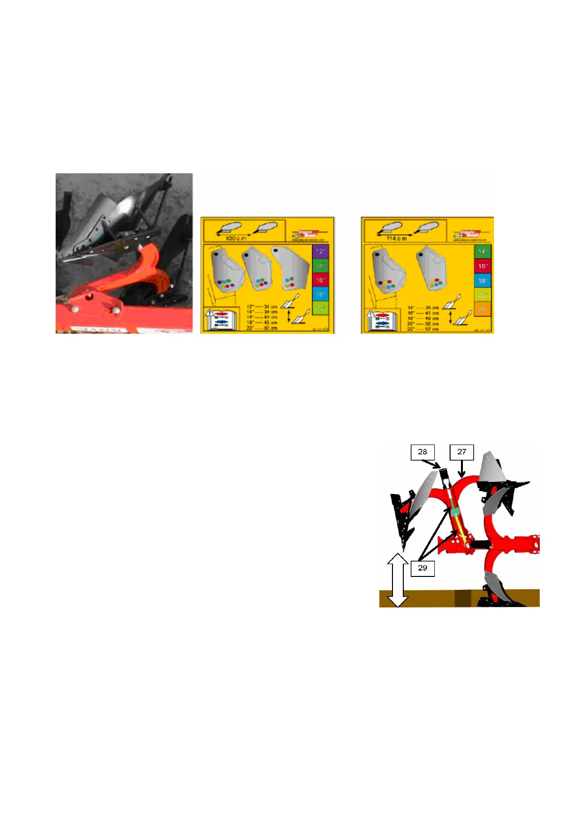
3.8. WORKING WIDTH
All plough bottom working width adjusting should be performed in 5 positions with the help of the
helival axle:
• 12’’ - 20’’ 100 cm for plough bottom distance.
• 14’’ - 22’’ 114 cm for plough bottom distance.
Every hole ont he beam bearing defines a definit
e working width.
The matrices above according to the plough bottom and color show the working width for evety
position.
If you have changed the working width you should adjust the deport again.
3.9. THE PRINCIPLE OF THE HYDRAULIC NON-STOP SECURITY
(Optional possibility)
The hydraulic Non-Stop security elements (27) mechanic
circulation connects with close hydraulic circuit which pressure
can be changed.
There is one hydraulic cylinder (28) behind every circulating
element. It is connected with the frame with the help of the double
tringle (29).
The mobile connection between the front part of the tube (30) and the frame of the plough is
performed with the help of the 4 axle journal (31).