H68.0.03.6C-02 Operating Manual GMI 15 plus page 5 of 12
_____________________________________________________ _____________________________________________________________________________
4 Display and Control Elements
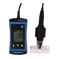
4.1 Display elements
Display of the current moisture or water
content
The name of the selected material
characteristic curve is displayed.
Moisture rating via bar graph.
The measuring value is ‘frozen‘ (hold-key)
on/off key,
Press long: switch device off
sort up
Material selection: upwards, p.r.t. chapter 6.4
hold:
press shortly: The measuring current value is ‚frozen‘ (hold-
function), ‘HLD’ is displayed
press for 2sec.: Zeroing function (p.r.t. chapter 6.5)
sort down
Material selection: downwards, p.r.t. chapter 6.4
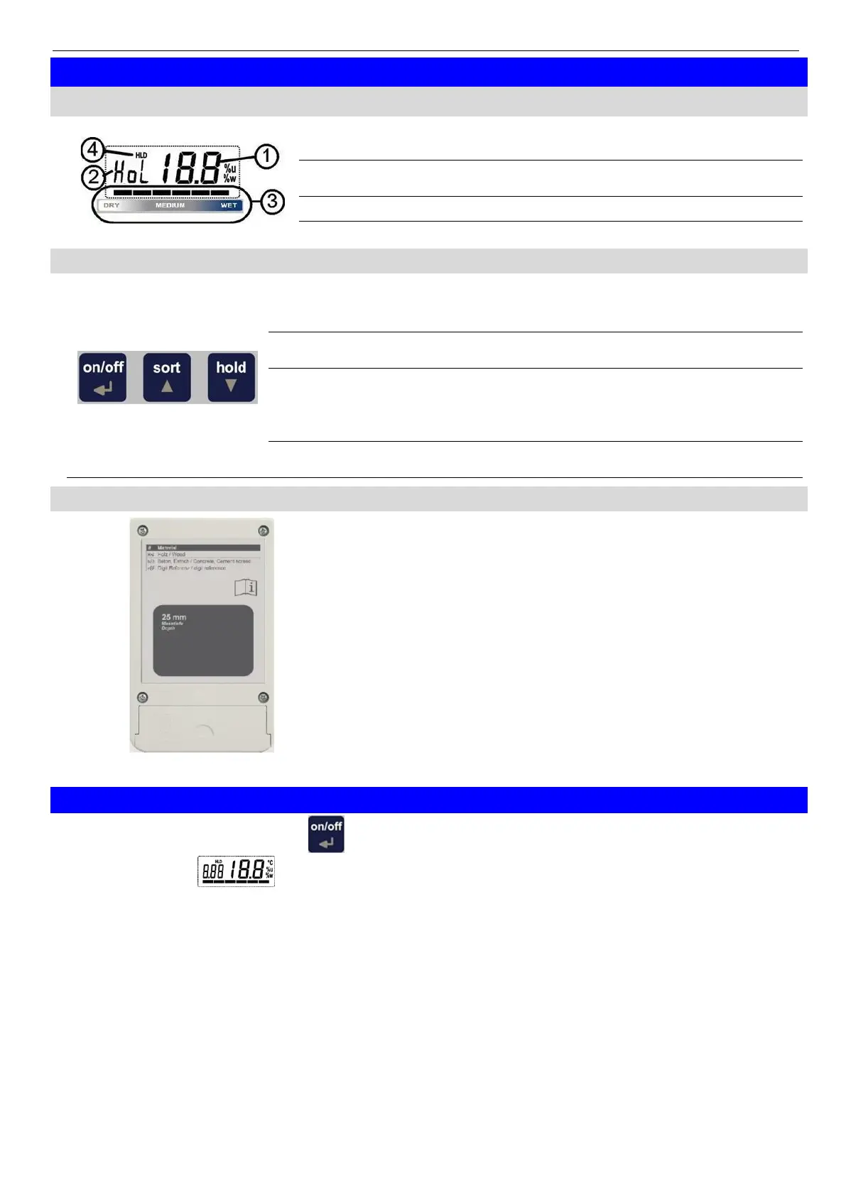
4.3 Measuring spot: rear side
The entire grey surface has to lie on the measured material
without any air gap.
The area “25 mm” (grey) mark the area under that it is
predominantly measured.
5 Start of Operation
Switch the device on with the key .
After segment test the device displays some information to its configuration:
S.25 if a slope adjustment has been made (p.r.t. chapter 11)
The device is ready for measuring afterwards.
 Loading...