EasyManua.ls Logo

Greystone CMD5B1 Series User Manual

Greystone CMD5B1 Series
5 pages
To Next Page IconTo Next Page
Page #1 background imageLoading...
Page #1 background image
Carbon Monoxide Transmitter Installation Manual
IN-CMD5B1-01-01 May 2, 2017 Page 1
Introduction
The CO Transmitter uses an electrochemical sensor to monitor the CO
level and outputs a 4-20 mA signal. The standard product features a 2-
wire loop-powered output. Optionally, the device may be configured with
an alarm relay and operates in 3-wire sourcing mode.
Before Installation
Read these instructions carefully before installing and commissioning the
CO transmitter. Failure to follow these instructions may result in product
damage. Do not use in an explosive or hazardous environment, with
combustible or flammable gases, as a safety or emergency stop device or
in any other application where failure of the product could result in
personal injury. Take electrostatic discharge precautions during
installation and do not exceed the device ratings.
Operation
In normal operation the sensor will measure the CO level in the surrounding air and output a proportional value on the 4-20
mA output. The CO measurement range is 0 to 300 ppm. An optional relay can be used to indicate an alarm condition. The
trip point for the relay can be programmed to three different settings with an on-board jumper. If the CO level exceeds the
trip point then the relay is activated. The relay will remain activated until the CO level drops below the (trip level –
hysteresis) where hysteresis is 3% or 9 ppm.
Start-up
Verify that the Carbon Monoxide Transmitter is properly wired according to the wiring diagrams and all connections are
tight. Apply power to the device and the sensor will begin reading the CO level and output the analog signal.
Mounting
The CO enclosure should be mounted on a flat surface three to five feet from the floor of the area to be controlled. Do not
mount the sensor near doors, opening windows, supply air diffusers or other known air disturbances. Avoid areas with
vibrations or rapid temperature changes.
Question and Answer IconNeed help?

Do you have a question about the Greystone CMD5B1 Series and is the answer not in the manual?

Greystone CMD5B1 Series Specifications

General IconGeneral
BrandGreystone
ModelCMD5B1 Series
CategoryTransmitter
LanguageEnglish

Summary

Introduction

Before Installation Safety

Device Operation and Mounting

Start-up Procedure

Details initial power application and sensor reading for the transmitter.

Mounting Guidelines

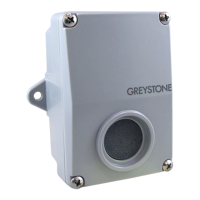
Instructions for physical placement to avoid air disturbances and ensure accuracy.

Wiring Instructions

2-Wire Loop-Powered Operation

Explains connections for 4-20 mA loop-powered operation using DC or AC power.

3-Wire Relay Model Operation

Details wiring for the relay model using AC or DC power, including signal output.

Relay Output Functionality

Describes the isolated relay contacts (NO, NC) for controlling alarms or ventilation.

Verifications and Calibration

Sensor Replacement Method

Describes a simple snap-mount sensor PCB replacement for pre-calibrated units.

Field Calibration Procedure

Outlines using a field kit with CO gas for calibration with or without cover.

Calibration Steps

Zero Adjustment

Setting the initial 4 mA output in clean air using the ZERO pot.

Span Adjustment

Adjusting the SPAN pot to read 250 ppm with gas supply after zeroing.

Common Specifications

Measurement Details

Covers measurement method, range, accuracy, and operating conditions.

Wiring and Enclosure

Specifies wiring connections, wire gauge, and enclosure dimensions.

Power Supply Requirements

Details power supply and consumption for 2-wire and 3-wire models.

Relay Specifications

Lists relay contact ratings, trip points, and hysteresis.