EasyManua.ls Logo

Grizzly MTS 30 AC - User Manual

Grizzly MTS 30 AC
196 pages
Go to English
Print Icon
To Next Page IconTo Next Page
Loading...
Motorsense
Kosa motorowa
Faux à moteur
Decespugliatore a motore
Brush cutter
Motorzeis
Motorová kosa
Motorový vyžínač
Variklinė žoliapjovė
DE
PL
MTS 30 AC
Originalbetriebsanleitung
Tłumaczenie oryginalnej instrukcji obsługi
Traduction de la notice d’utilisation originale
Traduzione delle istruzioni per
l’uso in originale
Translation of the original instructions for use
Vertaling van de originele gebruiksaanwijzing
Překlad originálního návodu k obsluze
Preklad originálneho návodu na obsluhu
Vertimas iš originalių
eksploatavimo instrukcijoje
FR
IT
GB
NL
CZ
SK
LT

Table of Contents

Question and Answer IconNeed help?

Do you have a question about the Grizzly MTS 30 AC and is the answer not in the manual?

Overview

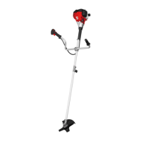
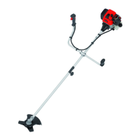
The Grizzly MTS 30 AC is a motorized strimmer designed for private use in gardens, specifically for cutting grass along borders, around trees, and fence posts. It can also be used with a metal cutting blade for cutting grass, weeds, or light plant growth. The device is intended for use by adults, with young people over 16 years old requiring supervision.

Function Description:

The MTS 30 AC is a hand-guided, portable motorized strimmer powered by an internal combustion engine that operates continuously during use. Power is transmitted to the cutting device via a clutch disc and a centrifugal clutch at high engine speeds. The cutting device features an automatic double-thread reel and an optional metal cutting blade. During operation, two plastic threads or four metal blades rotate around a vertical axis relative to the cutting plane. A protective cover shields the user from accidental contact with the cutting tool and from thrown objects.

Safety Functions:

  • On/off switch (No. 40): Located on the switching element (No. 22), this switch turns the engine off. It must be in the "I" position to restart the engine.
  • Throttle lock (No. 41): Prevents accidental acceleration of the engine. The throttle lever (No. 42) can only be operated when the throttle lock is depressed.
  • Protective covers (No. 15 & 20): These covers protect the operator from unintentional contact with the cutting tool and from thrown foreign objects.

Important Technical Specifications:

  • Engine: Single-cylinder two-stroke engine
  • Fuel Mix Ratio: 40:1 (petrol and two-stroke engine oil)
  • Engine Capacity: 30 cm³
  • Max. Engine Power: 1 kW (1.36 PS)
  • Engine Tick Over Speed: 3000 min⁻¹
  • Max. Shaft Speed: 10500 min⁻¹
  • Engine Speed at Recommended Max. Shaft Speed: 8000 min⁻¹
  • Fuel Consumption at Max. Engine Power: 0.438 kg/h
  • Specific Fuel Consumption: 0.434 kg/kWh
  • Tank Capacity: 500 cm³
  • Weight (without cutting tool, empty tank): 6.4 kg
  • Metal Cutting Blade Diameter: 230 mm
  • Thread Cutting Width: 430 mm
  • Thread Thickness: 2.0 mm
  • Thread Length: 2 x 3 m
  • Sound Pressure Level (LPA) (Trimmer Mode): 97.4 dB(A)
  • Guaranteed Sound Power Level (LWA): 112 dB(A)
  • Measured Sound Power Level (LWA): 109.7 dB(A); KWA=2 dB
  • Vibration (ah) (Left Handle, Trimmer Mode): 8.935 m/s²; Kh=1.5 m/s²
  • Vibration (ah) (Right Handle, Trimmer Mode): 9.839 m/s²; Kh=1.5 m/s²
  • Sound Pressure Level (LPA) (Scythe Mode): 99.5 dB(A)
  • Guaranteed Sound Power Level (LWA): 112 dB(A)
  • Measured Sound Power Level (LWA): 109.7 dB(A); KWA=2 dB
  • Vibration (ah) (Left Handle, Scythe Mode): 4.472 m/s²; Kh=1.5 m/s²
  • Vibration (ah) (Right Handle, Scythe Mode): 3.717 m/s²; Kh=1.5 m/s²

Usage Features:

  • Assembly: Before initial operation, the two-part shaft tube, handle, cutting device with protective cover, and carrying strap must be fitted. The fuel tank must be filled, and the equipment checked.
    • Two-Part Tube Assembly: Remove the transport cap (No. 29) from the bottom shaft tube (No. 13), loosen the tube fixing screw (No. 12) on the top shaft tube (No. 10), then plug the two shaft tubes together until the safety button (No. 30) clicks into place. Retighten the tube fixing screw.
    • Handle Fitting: Loosen the Allen screws (No. 31) on the top shaft tube (No. 10) and remove the handle holder (No. 32). Place the multifunction handle (No. 11) into the slot and secure it with the holder and screws. Push the accelerator handle (No. 51) onto the pipe end and screw it in place. Fix the accelerator cable (No. 8) with cable ties (No. 27).
    • Metal Cutting Blade Installation: If applicable, unscrew existing flanges. Screw the protective cover (No. 15) onto the cutting head holder (No. 19) using the provided screws (No. 34). Place the bottom flange (No. 33a), metal cutting blade (No. 18), and top flange (No. 33b) onto the cutting head holder. Screw on the metal cutting blade anticlockwise with the fixing nut (No. 35) and maintenance key (No. 26). Insert the splint (No. 23).
    • Reel Capsule Installation: Screw the protective cover/reel capsule (No. 15) onto the protective cover/metal cutting blade (No. 20) using the provided screws and nuts (No. 36). Screw the reel capsule (No. 16) anticlockwise onto the cutting head holder by hand. Remove the protective cap on the thread cutter (No. 14).
  • Fuel Filling: Use a 40:1 mix of unleaded petrol (min. 90 octane) and Grizzly two-stroke engine oil. Ensure good ventilation, do not smoke, and keep away from heat sources. Never fill the tank while the engine is running or hot. Open the tank cap (No. 37) carefully to relieve pressure. Fill the fuel mix into the tank (No. 2), wipe away any spills, and reclose the tank cap. Start the equipment at least 3 meters away from the filling location.
  • Starting the Engine:
    1. Ensure the protective cap on the thread cutter (No. 14) is removed.
    2. Place the device on a stable, level surface, ensuring the cutting tool does not touch objects or the ground.
    3. Set the on/off switch (No. 40) to "I".
    4. For a cold start, set the choke lever (No. 4) to "START". For a warm start, leave it at "RUN".
    5. Press the fuel pump (No. 7) 10 times.
    6. To engage the half-throttle lock, simultaneously press the throttle lock (No. 41), throttle lever (No. 42), and gas-locking knob (No. 43). Release the throttle lock and throttle; the half-throttle lock will engage.
    7. Hold the equipment firmly with one hand on the top shaft tube (No. 10) and pull the starter cable (No. 3) several times until the engine starts. Do not pull the starter cable out too far.
    8. Allow the engine to warm up for approx. 10 seconds.
    9. If the engine does not start, repeat steps 3 to 5.
    10. Attach the equipment to the carrying strap (No. 28) (see below).
    11. To mow, hold the throttle lock (No. 41) depressed and operate the throttle (No. 42). The choke lever (No. 4) will automatically jump to "RUN".
    12. To switch off the engine, set the on/off switch (No. 40) to "0".
  • Working with the Thread Reel: Hold the equipment at approx. 30° angle, swinging in semi-circular movements. For best results, cut grass up to 15 cm long. Extend the cutting thread by lightly tapping the cutting head on the ground.
  • Working with the Metal Cutting Blade: Use only on open, level areas. Inspect the area for obstacles. Hold the cutting head above the ground, swinging slowly like a scythe. Do not hold the cutting head at an angle.

Maintenance Features:

  • Cleaning: After each use, clean the cutting device and protective cover of grass and dirt. Do not spray with water or immerse in water. Do not use detergents or solvents.
  • Reel Change: Switch off the engine. Place the equipment on the ground, ensuring no fuel leaks. Unscrew the hand nut (No. 43) clockwise. Extract the thread reel (No. 17) from the reel capsule (No. 16). To install a new reel, thread both thread ends through the eyes (No. 44) in the reel capsule, press the reel into the capsule, ensuring the springs (No. 45) are correctly seated. Screw on the hand nut anticlockwise. Trim the thread cord to approx. 13 cm.
  • Air Filter Cleaning: Never operate without an air filter. Switch off the engine. Undo the screw (No. 46) on the filter housing (No. 47) and remove the air filter cover (No. 5). Remove the air filter (No. 48), clean it with soap and water, and let it dry. Never use petrol. Reinstall in reverse order. Replace if worn or damaged.
  • Spark Plug Change/Adjustment: Worn spark plugs or a large spark gap reduce engine performance. Switch off the equipment. Remove the ignition cable (No. 6) from the spark plug (No. 49). Unscrew the spark plug anticlockwise with the maintenance key. Check the spark gap with a feeler gauge (0.6-0.7 mm). Adjust if necessary by carefully bending the earth electrode. Clean the spark plug with a wire brush. Reinsert the cleaned/adjusted spark plug or replace it with a new one. Reattach the ignition cable.
  • Thread Cutter Sharpening: Wear protective gloves. Unscrew the thread cutter (No. 14) from the protective cover (No. 15). Fix it in a vice and sharpen the blade with a flat file, filing carefully in one direction only. Never use the equipment without a thread cutter or with a defective one.
  • Fuel Filter Change: Never operate without a fuel filter. Drain the fuel tank (No. 2). Pull the fuel suction head (No. 50) out with a hook and twist it off. Replace the fuel filter and put the suction head back in the tank.
  • Carburettor Adjustment: The carburettor is factory-preset for optimal performance. Any adjustments should be done by a specialist workshop.
  • Storage: Clean the equipment and accessories thoroughly. Store in a dry, dust-free place, out of reach of children. Do not wrap in plastic bags. Do not store on the protective cover; ideally, hang it from the top handle. For breaks longer than 3 months, drain the fuel tank, run the engine until it stops, and let it cool. Loosen the spark plug, pour a teaspoon of two-stroke oil into the combustion chamber, pull the starter cable slowly several times, and reinsert the spark plug.

Grizzly MTS 30 AC Specifications

General IconGeneral
BrandGrizzly
ModelMTS 30 AC
CategoryBrush Cutter
LanguageEnglish

Related product manuals