4
English
Application
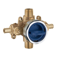
GrohFlex
TM
is a universal rough-in valve for thermostats and
Pressure Balance Valves. Type of use is specified by different
types of trims. To plan the piping, choose type of installation on
Pages 1 and 2.
The Concealed System can be used in conjunction with:
• Pressurised storage heaters
• Thermally controlled instantaneous heaters
• Hydraulically controlled instantaneous heaters
Operation with unpressurised storage heaters (displacement
water heaters) is not possible.
Specification
• Integral service stops
• Flow pressure:
-min 20 psi
- recommended 20 – 72.5 psi
greater than 72.5 psi, fit pressure reducing valve
• Max. operating pressure 125 psi
• Max. test pressure 500 psi
• Temperature
- max. (hot water inlet) 180 °F
• Water connection: cold - RH
hot - LH
Installation
Refer to the dimensional drawing on the front page.
Prepare the holes for the rough-in and slots for the pipes.
For different installation options, see the pre-drilled holes
in Fig. [1] and [2] on Page 3 and on the front page.
For mounting
• on the wall use back holes, see Fig. [1].
• on plasterboards wall use front holes, see Fig. [2].
Align the valve
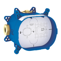
Place a spirit level on the tabs of the fitting template (blue box),
see Fig. [1].
Install the rough-in using the fitting template (blue box)
• The finished surface of the wall must lie within the area (A)
of the fitting template (blue box), see Fig. [3] and [4].
• The hot water supply must be connected on the left and the
cold water supply on the right, see Fig. [3].
Connect the pipes, see Figs. [3] and [4].
Check the installation options.
For possible combinations, see Pages 1 and 2.
A soldered connection is not available.
Open the cold and hot water supply and check the fitting
connections for leakage.
Flush the pipes thoroughly, see Figs. [5] and [6].
1. Remove the cover, see Fig. [5].
2. Open the hot and cold water supply. This rough-in is
combined with integrated service stops for opening and
closing, see Fig. [6]. Flush the pipes thoroughly.
Plaster and tile the wall
Do not cut the fitting template (blue box) before final
installation.
 Loading...