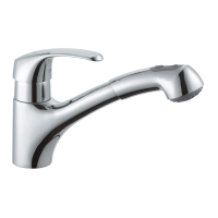
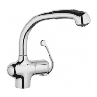
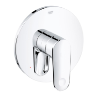
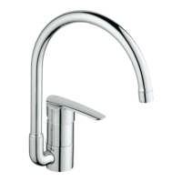
This document describes the GROHE Wave single-lever mixer, model number 32 449, designed and engineered in Germany.
Function Description
The GROHE Wave single-lever mixer is a faucet designed for use with pressurized storage heaters or instantaneous heaters. It is not compatible with unpressurized storage heaters (open water heaters). The mixer allows for continuous and individual adjustment of the water flow rate. The swivel spout's range of rotation can be adjusted via a stop mechanism.
Important Technical Specifications
- Model Number: 32 449
- Flow Pressure: Optimal operation requires a flow pressure between 1 and 5 bar. For higher flow pressures, installing a pressure-reducing valve is recommended.
- Net Weight: 2.5 kg
- Cartridge: The mixer is equipped with a cartridge (part number 46 048) for controlling water flow and temperature.
- Mousseur/Aerator: Part number 13 928.
- Connections: Features pressure hoses with seals (part number I) for connection to service valves.
- Adjusting Screw for Flow Rate: Requires a 2.5mm Allen key for adjustment.
- Set Screw for Lever: Requires a 3mm Allen key for removal.
- Swivel Spout Rotation: Adjustable via stop A, with a range of 0° to 360° or 150°.
Usage Features
Installation
- Preparation: Before installation, thoroughly flush cold and hot water lines to remove contaminants. Avoid damaging the fitting's surfaces with tools; do not use toothed pliers.
- Swivel Spout Installation: Install the swivel spout. The rotation range can be set using stop A.
- Worktop Installation:
- Push O-ring B onto the fitting.
- Insert the fitting through hole C in the worktop.
- From below, fit sealing washer D and mounting set E.
- Fasten the fitting with nut H.
- Sink Installation:
- Push O-ring B onto the fitting.
- Insert the fitting through hole F in the sink.
- From below, fit support plate G, sealing washer D, and mounting set E.
- Fasten the fitting with nut H.
- Hose Connection: Screw the fitting's pressure hoses with seal I to the service valves. Ensure hoses are not bent or twisted.
- Leak Check: Open the cold and hot water supply and check all connections for watertightness.
Flow Rate Limitation
The mixer includes a flow rate limiter, factory-set to the maximum flow. This feature allows for stepless and individual reduction of the flow rate.
- Note: The use of flow rate limiters is not recommended with hydraulic instantaneous heaters.
- Adjustment Procedure:
- Lever out plug J.
- Remove set screw K using a 3mm Allen key.
- Remove lever L.
- Remove cap M.
- Adjust the flow rate by turning the adjusting screw with a 2.5mm Allen key.
Operation
The document indicates that the fitting should be operated as shown in the accompanying illustrations (not provided in text).
Maintenance Features
Troubleshooting
Fault: Flow rate noticeably reduced or changed spray pattern
- Insufficient supply pressure: Check the upstream installation.
- Blocked/dirty mousseur (13 928): Clean or replace the mousseur.
Fault: Fitting housing leaking
- Loose cartridge screws (46 048): Tighten the cartridge screws alternately.
- Damaged seals at cartridge base or dirt particles on sealing surfaces:
- Close the cold and hot water supply.
- Check and clean sealing surfaces, or replace the cartridge completely.
- Impermissible operating conditions (e.g., hot water temperature above 80 °C, pressure surges in upstream installation):
- Ensure operating conditions are correct.
- Replace the cartridge completely if necessary.
For faults not described, contact a qualified installer.
Care and Recycling
Refer to the accompanying Care Instructions for detailed care guidelines (not provided in text). When disposing of the fitting, observe the valid national regulations.