4
Operation
a) Lever set
Slide lever to right = open (water flow)
Slide lever to left = close
Slide lever towards front = cold water
Slide lever towards back = hot water
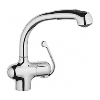
b) Handspray,
see Fig. [8].
Water will always flow from the aerator first.
Diverter button:
Turning off the mixer automatically diverts the water
flow from handspray to aerator.
c) Stopcock for dishwasher
Flow rate limiter
This mixer is fitted with a flow rate limiter, permitting an
infinitely variable reduction in the flow rate by up to
50%.
The highest possible flow rate is set by the factory
before despatch.
Please proceed as follows to limit flow:
1.With a 3mm socket spanner, remove fixing
screw (O), see Fig. [9].
2.Pull off lever (P).
3.Turn cap (R) through 180
°
(slot pointing upwards)
and pull off the cap.
4.Change flow rate by turning hexagon socket screw
clockwise with a 1.5mm socket spanner. Turn clock-
wise (to reduce flow) or anticlockwise (to increase
flow), see Fig. [10].
Assemble in reverse order.
Maintenance
Shut off the hot and cold water supply.
I. Cartridge,
see fold-out page III, Fig. [11].
1.With a 3mm socket spanner, remove fixing
screw (O).
2.Pull off lever (P).
3.Turn cap (R) through 180
°
(slot pointing upwards)
and remove the cap.
4.Remove fixing screw (S) and pull off adjusting
lever (T).
5.Screw out screws (U) and remove cartridge
assy (V).
6.Renew cartridge assy (V) or seals (V1).
Assemble in the reverse order.
Care must be taken to ensure that the seals (V1) in the
cartridge engage the grooves in the body. Install
screws (U) and tighten
evenly and alternately
.
II.Ceramic headpart,
see Fig. [12].
1.Remove top plate (W).
2.Using screwdriver, lever off connecting cap (W1)
and remove.
3.With a 17mm open-ended spanner, remove ceramic
headpart (X).
4.If necessary relace ceramic headpart (X).
Assemble in the reverse order.
To install the handle, close the headpart (X) and
depress the retaining cap (W1); the notch (W2) must
face upwards.
III.Strainer and rose,
see Figs. [13] and [14]
1.Unscrew rose (Y) using 24mm open-ended or
socket spanner, see Fig. [13].
2.Clean strainer (Y1) and rose (Y), renew strainer if
necessary.
3.With SpeedClean nozzles simply rub fingers over
rose to remove limescale, see Fig. [14].
We guarantee that the SpeedClean nozzles will
function unchanged for a period of five years.
Assemble in reverse order.
Inspect and clean all parts, replace as necessary and
grease with special grease (order no. 18 012).
Replacement parts,
see fold-out page I ( * = special
accessories).
Care
For directions on the care of this single-lever mixer,
please refer to the accompanying Care Instructions.
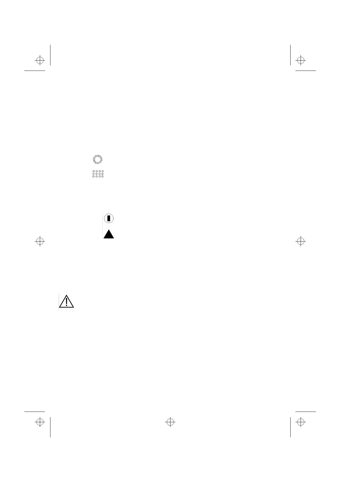
When the symbol
is closed.
points upwards, the valve
When the symbol
is open.
points upwards, the valve
Press symbol
= switches to spray flow
Press symbol = switches from spray to
aerator flow
The use of flow rate limiters in combination
with hydraulic instantaneous water heaters
is not recommended.
I954561.b : I95456GB.FM Page 4 Friday, April 24, 1998 1:17 PM