Anschlüsse und Einstellungen / Connections and functions / Connexion et réglages
1
2
3
4
5
6
7
8
9
Anschlüsse und Einstellungen / Connections and functions
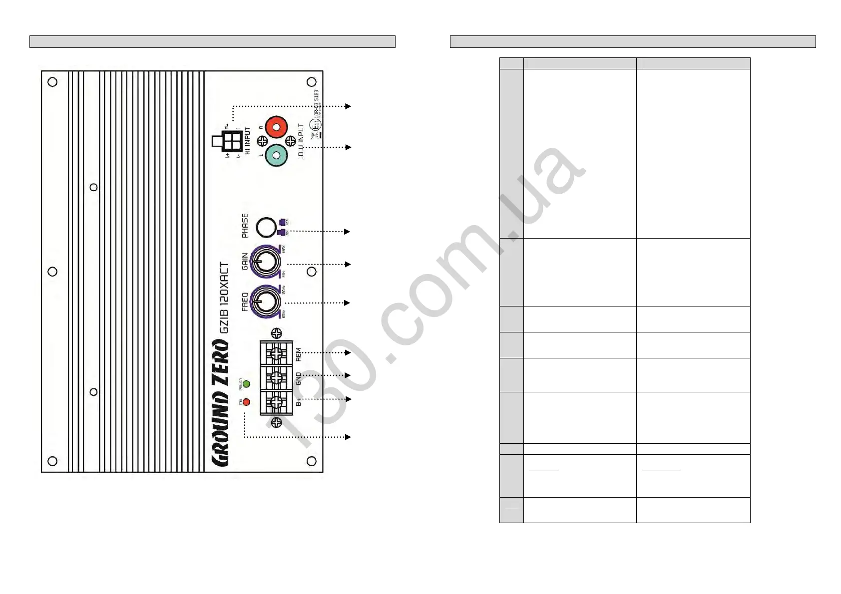
No Erklärung Declaration
1
Hi
h Level Ein
än
e
Hiermit lässt sich der Verstärker
mittels Hochpegel- Signal
betreiben. Verbinden Sie hierzu
die High Level Eingänge direkt
mit den Lautsprecher-ausgängen
der Headunit oder eines
vorhandenen, fahrzeug-
spezifischen Aktivsystems.
Auto-On
Die Auto-On Funktion der High
Level Eingänge ermöglicht den
Betrieb ohne zusätzlichen
Remote Anschluß. Das Gerät
schaltet ein, sobald ein Signal an
den High Level Eingängen
anliegt.
Nutzen Sie keinesfalls die
High-und die Low Level-
eingänge gleichzeitig.
Hi
h Level Input
High level input terminal should
be connected with the speaker
output of the Headunit or a
carspecific active system.
Auto-On
The Auto-On function allows to
use the amplifier without
additionally remote connection.
The unit automatically turns on
as soon as a signal is received.
Do not use the High- and
Low Level Input together at
the same time!
2
Low Level Ein
än
e
Eingänge für den linken (L) und
rechten (R) Kanal des
Verstärkers. Die Vorverstärker
Ausgänge der Signalquelle
(Headunit) oder einer externen
elektronischen Weiche müssen
hier angeschlossen werden.
Low Level Input
Left (L) and Right (R) channel
inputs of the amplifier system.
Pre- amplifier outputs of a
source (head unit) or of an
external electronic crossover
must be connected to these
inputs.
3
Phase Shift
Phasen-Schalter: 0° (Nor.) oder
180° (Rev.) schaltbar.
Phase Shift
Phase switch: 0° (Nor.) or 180°
(Rev.) switchable.
4
Input Level
Zum einstellen der
Eingangsempflindlichkeit
Input Level
Knob for adjusting the input
sensitivity
5
Weiche
Zur Einstellung der oberen
Grenz-Frequenz von 40 Hz ~
160 Hz.
Crossover
To adjust the cut-off frequency
from 40 Hz ~ 160 Hz
6
REM -> Remote
Antennenanschluss
Wichtig
Bei Benutzung des High Level
Eingangs wird der Remote
Anschluß nicht benötigt.
REM -> Remote antenna
terminal
Important
The remote connection is not
needed if using the High Level
In.
7
GND -> Masse Anschluss GND -> Ground connection
8
B+ -> +12 Volt
Wichtig:
Bitte benutzen Sie mind.
6 mm² Kabel für die
Spannungsversorgung
B+ -> +12 Volt
Important:
Please use min. 6 mm² cable
for the power supply.
9
Statusanzei
e LEDs
Betrieb (grün)
Fehler (rot)
Power / Protection LED
Power (green)
Protection (red)

 Loading...