6
English (US)
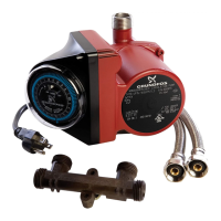
Fig. 6 Connect bypass valve, flex hoses, and fittings as shown
Installing the bypass valve
1. Connect the 1/2" X 1/2" flex hoses to the
ports on the bypass valve marked "HOT
OUT" and "COLD OUT". See fig. 6.
2. Connect the 1/2" x 3/8" flex hoses to the
ports on the bypass valve marked "HOT IN"
and "COLD IN". See fig. 6.
3. Connect the 1/2" hose fitting from the "HOT
OUT" port on the bypass valve to the left
side of the faucet. See fig. 6.
4. Connect the 1/2" hose fitting from the "COLD
OUT" port on the bypass valve to the right
side of the faucet. See fig. 6.
5. Connect the 3/8" hose fitting from the "HOT
IN" port on the bypass valve to the left angle
stop valve. See fig. 6.
6. Connect the 3/8" hose fitting from the "COLD
IN" port on the bypass valve to the right
angle stop valve. See fig. 6.
7. Open both hot and cold water angle stop
valves. Check for leaks.
8. Bypass valve may be mounted to the wall
with supplied mounting screws if desired;
two-hole mounting bracket flush with wall.
See fig. 7.
9. For troubleshooting, see section 7. Fault
finding.
Fig. 7 Correct installation of bypass valve
TM05 8976 3013
1/2" x 1/2"
flex hose
1/2" x 1/2" flex
hose
Hot water
OUT
Cold water
OUT
To hot water faucet
To cold water faucet
1/2" x 3/8"
flex hose
1/2" x 3/8"
flex hose
Hot water IN Cold water INBypass valve
TM05 8977 3013
 Loading...