English (GB)
7
English (GB) Installation and operating instructions
Original installation and operating instructions.
CONTENTS
Page
1. Symbols used in this document
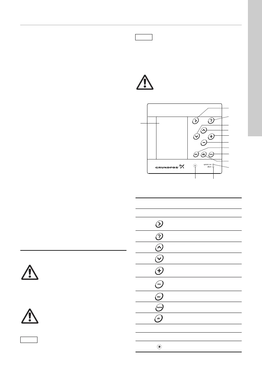
1.1 General description
The CU 351 is a flexible control unit for control and
monitoring of up to six pumps.
Fig. 1 CU 351
1. Symbols used in this document
7
1.1 General description
7
1.2 Indicator lights
8
1.3 Terminals
8
1.4 Potentially explosive environments
8
2. Identification
8
2.1 Type key
8
3. Installation
8
3.1 Location
9
3.2 Enclosure class
9
3.3 Terminals
9
4. Mechanical installation
9
5. EMC-correct installation
9
5.1 GENIbus connection to IO 351 and E-
pumps
10
5.2 External GENIbus module
10
6. Start-up
10
7. Functions of indicator lights
11
8. Technical data
11
9. Electrical data
11
9.1 Digital inputs
12
9.2 Analog inputs
12
9.3 Digital outputs (relay outputs)
12
9.4 Conductors
12
9.5 Terminal groups
12
10. Overview of inputs and outputs
13
11. Service
14
12. Maintenance
14
13. Replacing the CU 351
14
14. Dimensions
14
15. Disposal
14
Warning
Prior to installation, read this
installation and operating instruction.
Installation and operation must comply
with local regulations and accepted
codes of good practice.
Warning
If these safety instructions are not
observed, it may result in personal
injury!
If these safety instructions are not
observed, it may result in malfunction
or damage to the equipment!
Notes or instructions that make the job
easier and ensure safe operation.
Warning
If the CU 351 is used in a manner not
specified by the manufacturer, the
protection provided by the CU 351 may
be impaired.
TM03 1304 1705
Pos. Description
1LCD display
2
Changes to next column in menu
structure
3 Changes to help text
4 Goes up in lists
5 Goes down in lists
6
Increases the value of a selected
parameter
7
Reduces the value of a selected
parameter
8 Goes one display back
9 Goes back to the Status menu
10 Saves a value
11 Green indicator light (operation)
12 Red indicator light (alarm)
13 Changes the contrast of the display