English (GB)
16
8. Commissioning
The diagram in fig. 28 is used as reference.
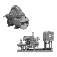
8.1 Overview of a firefighting application
Fig. 28 Overview of a firefighting application
TM06 1523 2414
M
10
13
3
6
22
26
23
24
25
17
15
12
16
14
9
2
19
18
21
1
4
5
7
8
9
11
Discharge to fire protection system
Suction from
tank or city
supply
Test and
relief
piping
return to
tank
Pos. Description Pos. Description Pos. Description
1
OS&Y (outside screw and yoke)
gate valve (suction control valve)
10 Test header 19
Isolation valve (jockey pump
suction)
2 Eccentric reducer 11
Indicating gate valve or butterfly
valve (discharge control valve)
20
Check valve (jockey pump
discharge), not displayed
3 Suction pressure gauge 12 Flowmeter 21
Isolation valve (jockey pump
discharge)
4 Discharge pressure gauge 13
Indicating gate valve or butterfly
valve (flowmeter)
22 Check valve (FDC)
5 Automatic air release 14 Pump controller 23 Fire department connection
6 Pressure relief valve 15
Pressure maintenance pump
controller (jockey pump)
24 Diesel fuel tank
7 Relief cone 16 Pressure sensing line (fire pump) 25 Diesel drive exhaust silencer
8 Check valve (pump discharge) 17
Pressure sensing line (jockey
pump)
26 Batteries
9
Indicating gate valve or butterfly
valve (test header)
18
Pressure maintenance pump
(jockey pump)
 Loading...