English (GB)
21
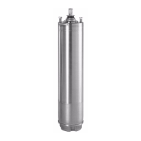
One yellow indicator light permanently
on.
High motor temperature (65, 66)
The motor temperature is too high. a) Check that the ambient temperature is within
the specified range.
b) Check that the pump is not covered by dust, dirt
or other foreign matter which reduces the air
cooling of the pump.
c) If none of the above causes are present,
replace the motor.
Internal communication fault (76)
Communication fault between different
parts of the electronics.
a) Replace the terminal box.
Soft pressure buildup, timeout (215)
The system has been in the mode "soft
pressure buildup" longer than the set time
limit.
a) Check the system for leakages.
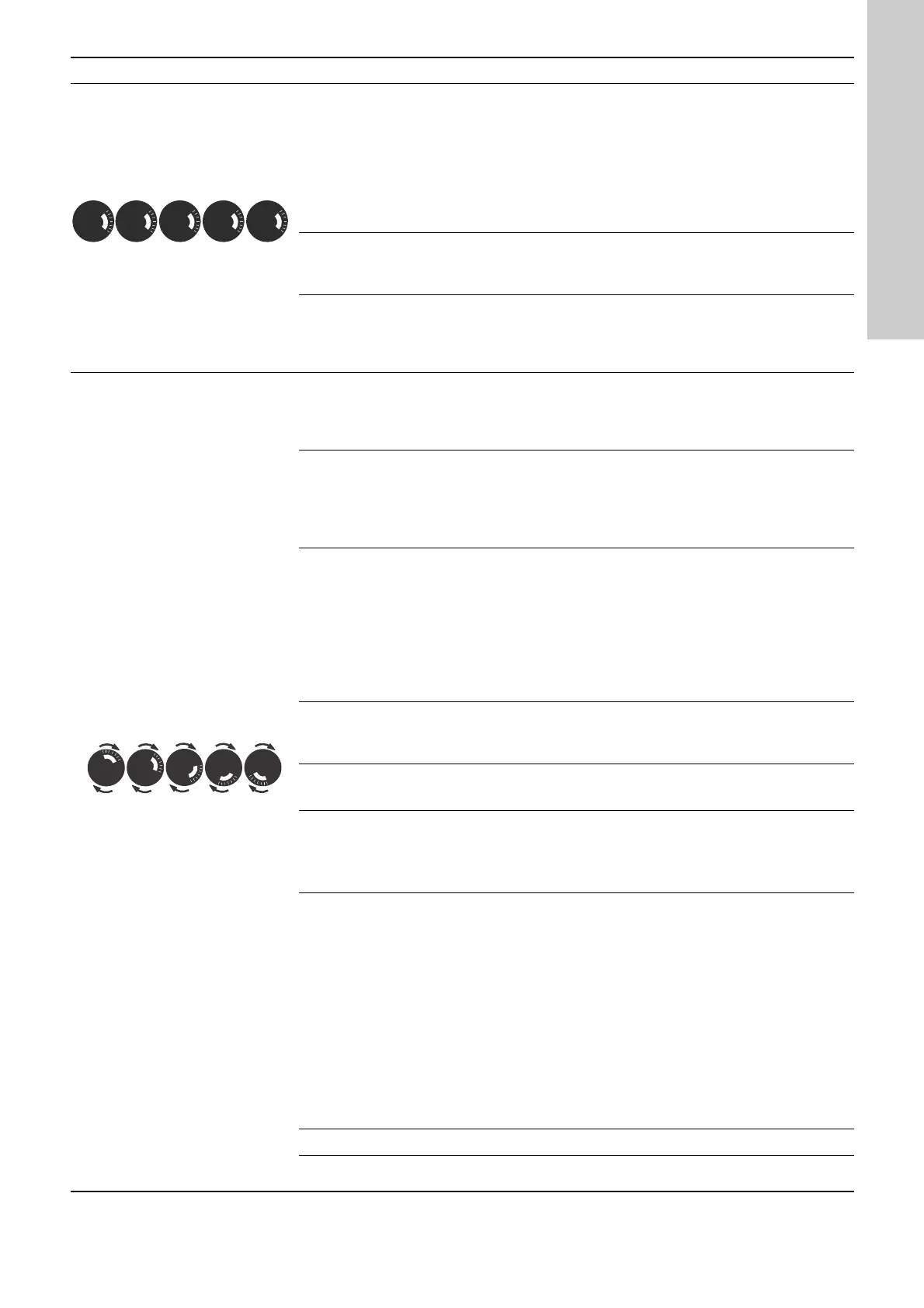
One yellow indicator light rotating in
the direction of rotation of the motor
when seen from the non-drive end.
Replace the motor bearings (30)
The bearings must be replaced. a) Follow the instructions for the pump. See
section 7.12 Replacing the bearings (MGE 100
and below).
Internal sensor fault (88)
The pump is receiving a signal from the
internal sensor which is outside the
normal range.
a) Check that the plug and cable are connected
correctly to the sensor. The sensor is on the
back of the pump housing.
b) Replace the sensor.
Pt100/1000 sensor 1 (91) and 2 (175)
Pt100/1000 input 1 is receiving a signal
which is outside the normal range.
a) Check that the sensor resistance corresponds
to approximately 100 or 1000 ohm. If not,
replace the sensor.
b) Check the sensor cable for damage.
c) Check the cable connection at the pump and at
the sensor. Correct the connection, if required.
d) Replace the sensor.
Supply fault, 5 V (161)
Fault in the output voltage to sensor or
potentiometer.
a) Check the output voltage and wire to sensor or
potentiometer.
Supply fault, 24 V (162)
Fault in the output voltage. a) Check the output voltage and wire.
Signal fault, LiqTec-sensor (164)
The pump is receiving a signal from the
LiqTec sensor which is outside the normal
range.
a) Check that the plug and cable are connected
correctly to the sensor.
b) Replace the sensor.
Signal fault, sensor 1 (165), 2 (166) and 3 (167)
Analog input 1, 2 or 3 is receiving a signal
which is outside the normal range.
a) Check that the setup of the analog input
corresponds to the sensor output as regards
electrical characteristics (0.5 - 3.5 V, 0-5 V, 0-10
V, 0-20 mA or 4-20 mA). If not, change the
setting, or replace the sensor with one that
matches the setup.
b) Check the sensor cable for damage.
c) Check the cable connection at the pump and at
the sensor. Correct the connection, if required.
d) Check if the sensor has been removed, but the
input was not deactivated.
e) Replace the sensor.
Limit 1 exceeded (190) and limit 2 exceeded (191)
Limit 1 or 2 has reached the limit for
warning/alarm.
a) Identify and remove the fault cause.
Grundfos Eye Condition/cause Remedy
 Loading...