English (GB)
24
9.3.1 Checking input and outputs
Pt100/1000
Use a 100 Ω resistance and decide on the basis on the motor
settings which value this resistance will show in the display when
connected to the terminals instead of the Pt100/1000 sensor.
Analog input, AI
It is possible to measure on the analog input to determine if its
function is correct.
During current state, a 292 Ω resistance in the input converts a
current signal (e.g. 0-20 mA) from the sensor to a voltage signal
for the processor.
Measure the voltage across the input and read the current in the
circuit by means of Grundfos GO Remote or PC Tool. The current
value must be equal to voltage divided with resistance.
Alternatively, a milliammeter can be connected in series with the
circuit.
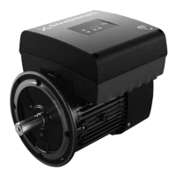
Fig. 55 Measuring on analog input
Next step is to test the input in voltage state. Change the setup of
the input to voltage state (0-10 V). Fit a jumper between terminal
5 (+5 V) and the analog input. 5 V must now be read be means of
PC Tool.
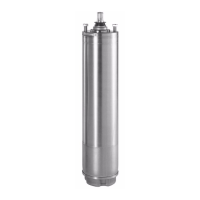
Fig. 56 Testing the input during voltage state
Change the setup of the input to current state and measure on
the input using an ohmmeter. The resistance must be 292 Ω. In
voltage state, the resistance is 122 kΩ.
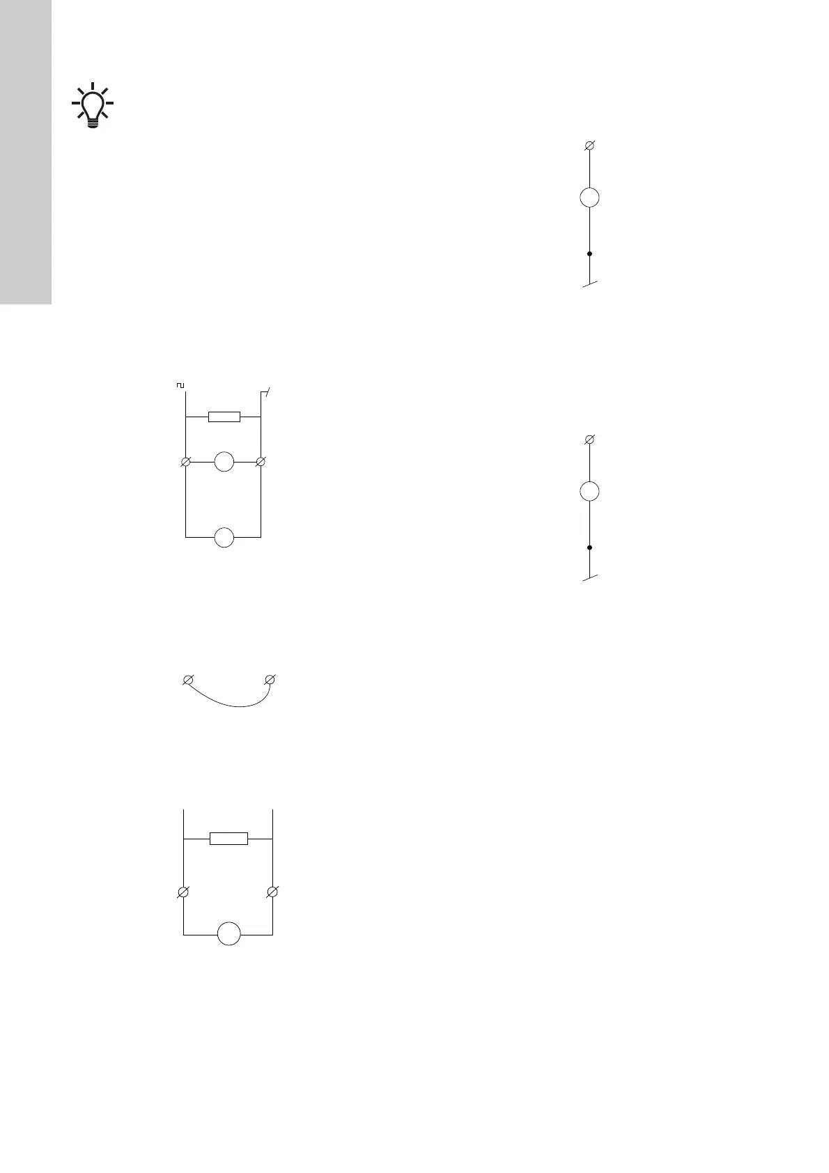
Fig. 57 Measuring resistance in current and voltage state
Analog output, AO
The analog input is protected against short circuit and will shut
down the signal in case of short circuit. If you suspect a short
circuit, remove the load and compare the value read via PC Tool
with the value measured by means of the measuring instrument.
If the values are not identical, the module is defective.
Digital input, DI
See the settings of the input in PC Tool.
Connect the digital input to frame (GND) by means of an
ammeter. The value measured must now be approximately 12
mA. Check that PC Tool shows a corresponding value.
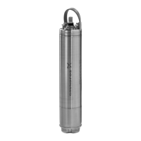
Fig. 58 Testing the digital input
Digital output, DO/open collector, OC
See the settings of the output in PC Tool.
Measure the output. If the value in PC Tool differs from the value
measured with the measuring instrument, remove the load. If the
values still differ, the module is defective.
The voltage of an active output is approximately 5 V.
Fig. 59 Measuring voltage on the digital output
LiqTec sensor
Connect a new LiqTec sensor to check the input. Immerse the
sensor into water and take it up. The motor must now report fault
within 20 seconds.
Signal relay
See the settings of the output in PC Tool.
Check if the relay reacts to the signals of the controller according
to the configuration of the controller.
CIM
Test the CIM module according to its manual.
Radio
If there are problems in the radio connection between Grundfos
GO Remote and the motor, remove the terminal box cover. See
section 7.1 Replacing the terminal box cover. Replace the control
panel if there is still no connection. See section 7.4 Replacing the
control panel.
Battery
Switch off power to the motor for a short period. When you switch
on the power to the pump again, adjust the clock.
Control panel (HMI)
Check the flat cable to the functional module. Replace the control
panel if the connection is correct, and it did not solve the problem.
Make a copy of motor settings.
TM05 7115 0613TM05 7116 0613TM05 7117 0613
TM05 7118 0613TM05 7118 0613
 Loading...