15
English (US)
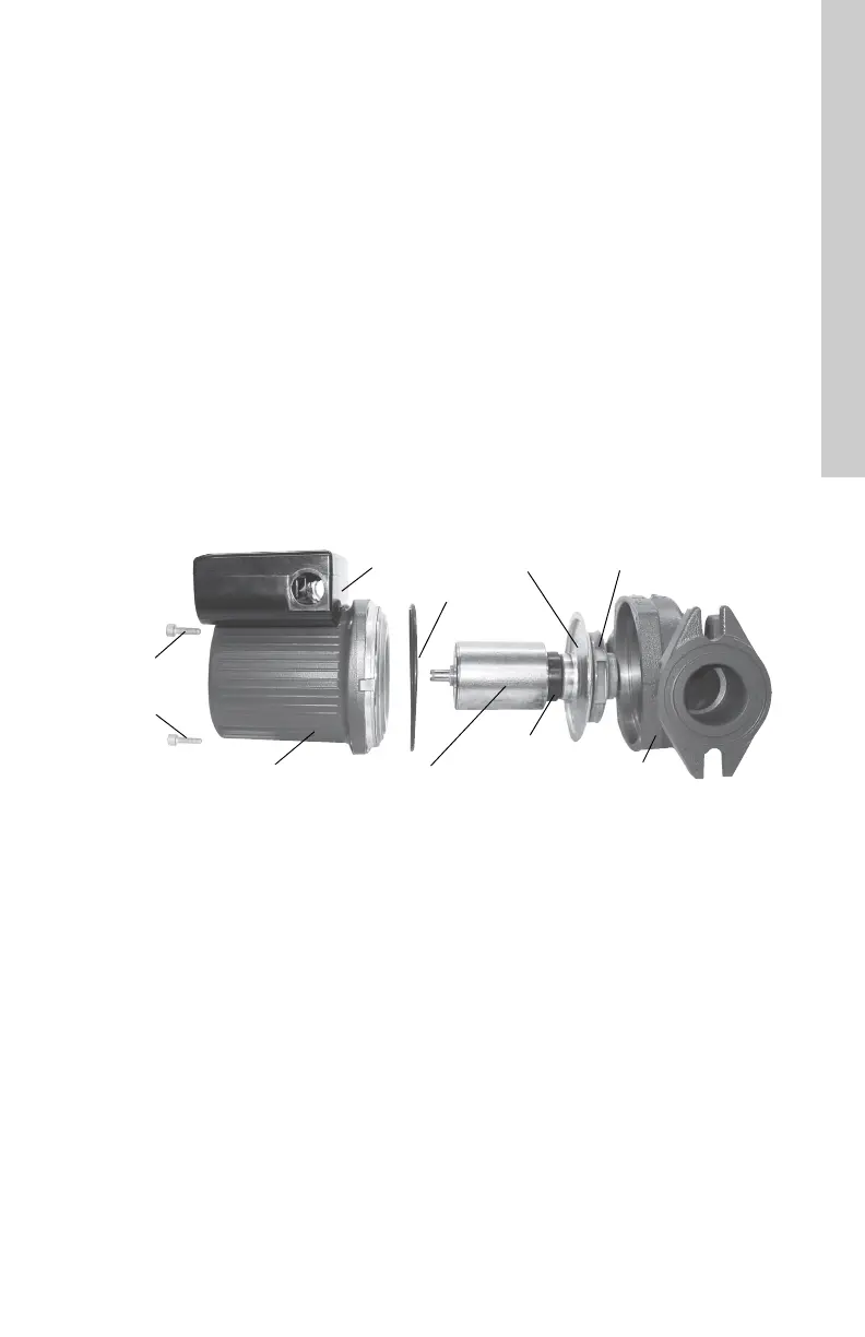
8.2 Fitting the pump head
1. Carefully remove the new pump head
assembly from its packaging. Separate the
impeller/rotor assembly from the new pump
head.
2. While holding the thrust bearing plate,
carefully place the impeller/rotor assembly
into the pump housing. The bearing plate
should fit snugly into the lowest machined
surface in the pump housing.
3. Ensure that the impeller/rotor assembly can
rotate freely.
4. Place the O-ring over the rotor and locate it
into the inner diameter of the pump housing.
5. Carefully place the pump head housing over
the rotor and rotate it so the terminal box is
in the position you wish; see section
5.2.1 Rotating the terminal box.
6. Ensure that the pump head housing is
properly seated on the pump housing. Do
not force the two together - if there is
binding, disassemble them and repeat steps
2 to 6. Cross-tighten the allen-head screws
evenly.
Torque to: 7 ft lb / 9.5 Nm.
7. Check to make sure the rotor turns freely. Do
this by removing the vent plug in the middle
of the pump nameplate. Insert a
medium-size, flat-blade screwdriver into the
slot at the exposed end of the shaft. Gently
turn the shaft. If it does not turn easily,
repeat steps 1 through 6 above. If the rotor
spins freely, proceed to step 8. Do not put
the vent plug back into the pump until the
end of step 10.
8. The position of the nameplate can be
changed by easing the outer edge of the
plate at the cutout with a screwdriver. Turn
the nameplate to the required position and
push into place.
9. Follow electrical instructions in section
5.3 Electrical connection.
10. Refill the system, open the isolation valves
and vent the system. Also allow air to vent
out of the pump, once water flows out the
vent hole, replace the vent plug removed in
step 7. See additional instructions in section
6.1 Vent the piping system.
Fig. 17 Removing and fitting the pump head
TM04 5635 3609
Terminal box
Stator housing Rotor assembly
ImpellerBearing plate
O-ring
Pump housing
Thrust bearing
Allen
screws (4)
5 mm
 Loading...