Do you have a question about the Grundig 32 GLX 2500 and is the answer not in the manual?
Important safety and handling instructions before operating or servicing the unit.
Guidelines for disconnecting and reconnecting leads to avoid damage and ensure proper function.
Proper procedure for using oscilloscopes and test probes to prevent component damage.
Information about the approximate nature of measured values provided in diagrams.
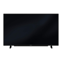
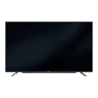
Details on different manufacturers' displays and their impact on chassis and software.
Guidance on identifying and using product codes and display variants for service.
Comprehensive specifications for various TV models, including display, picture, and tuning features.
Detailed features and connectivity options for audio systems and front panel ports.
Information on power requirements, cabinet dimensions, and weight for different models.
Overview of all input/output ports located on the rear of the television unit.
Diagram illustrating all rear panel input and output connections for the television.
Diagram showing the location and function of buttons on the television's front panel.
Explanation of remote control buttons and their functions for TV operation.
Accessing and navigating the special functions menu for settings like language and timer.
Instructions for setting the on/off timer and selecting programs for automatic startup.
How to activate and deactivate the keypad lock and block programs for children.
Steps for connecting a PC to the television using VGA and audio cables.
Guide to selecting the PC channel and adjusting picture settings for PC input.
Navigating the 'Features' menu for language, timers, and panel lock settings.
Instructions for selecting the desired language for the on-screen menu.
Setting switch-on/off times and program selection for automatic TV operation.
Activating and deactivating the keypad lock for parental control.
Blocking programs unsuitable for children by selecting channels and activating lock.
Unblocking programs by selecting the channel and deactivating the parental lock.
Explanation of remote control button usage within the service mode.
Table detailing fundamental adjustments available in the service mode for various models.
Information on how to check the software version displayed in the service menu.
Instructions on changing the remote control code and accessing service menu.
Steps for performing automatic channel scanning and program search.
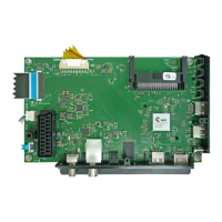
Visual guide to component placement on the YRQ190R-5 chassis's circuit board.
Detailed view of components on the component side of the YRQ190R-5 board.
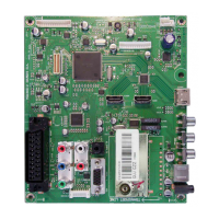
Visual guide to component placement on the YRQ190R-7 chassis's circuit board.
Detailed view of components on the component side of the YRQ190R-7 board.
Schematic of the power supply unit for the YRQ190R-5 chassis.
Schematic of the power supply unit for the YRQ190R-7 chassis.
Circuit diagram for SCART, VGA, and AV input/output connections on YRQ190R-5.
Circuit diagram detailing the HDMI input/output connections for the YRQ190R-5 chassis.
Circuit diagram for SCART, VGA, and AV input/output connections on YRQ190R-7.
Circuit diagram detailing the HDMI input/output connections for the YRQ190R-7 chassis.
Schematic of the tuner section for the YRQ190R-5 chassis.
Schematic of the scaler section for the YRQ190R-5 chassis.
Schematic of the tuner section for the YRQ190R-7 chassis.
Schematic of the scaler section for the YRQ190R-7 chassis.
Schematic of the audio processing and amplifier circuits for the YRQ190R-7 chassis.
| Screen Size | 32 inches |
|---|---|
| Resolution | 1366 x 768 pixels |
| Display Technology | LED |
| Refresh Rate | 50 Hz |
| HDMI Ports | 2 |
| USB Ports | 1 |
| Smart TV | No |