Do you have a question about the Grundig 32 VLE 786 BL and is the answer not in the manual?
Provides essential safety and handling instructions before opening the cabinet and during measurements.
Details features like Parental Control and Cloning Function for data backup and transfer.
Emphasizes proper routing of leads after repair to prevent future failures.
Advises on oscilloscope probe settings (10:1) and capacitor discharge to avoid component damage.
Requires re-setting all parameters in Service Mode after chassis board replacement.
Guides on safely removing the front cabinet of the Backlight Modul System.
Instructions for removing the WLAN module before disassembling the metal back cover.
Explains how to identify and use product codes and display variants for spare parts and software.
Details panel type, backlight, screen format, and 3D capabilities.
Lists picture enhancement features like Motion Picture Improvement and Digital Color Transition.
Covers audio modes, speakers, SRS, Dolby Digital, and sound presets.
Outlines EPG, timers, Teletext, HbbTV, and child lock features.
Details DVB reception compliance, channel search, and EPG data support.
Identifies and explains all external input/output ports on the TV.
Explains the function of the power switch and multi-function switch on the TV set.
Details the operations and menu navigation using the TV's multi-function switch.
Guides through the initial setup process including language, country, and user mode selection.
Provides step-by-step instructions for establishing an automatic wired network connection.
Details the process for automatic network connection via Wi-Fi using a password.
Instructions for tuning TV channels via satellite, including automatic channel search.
Outlines the two methods for configuring wired network connections: automatic and manual.
Details the automatic Wi-Fi connection process using a network password.
Step-by-step guide for connecting to a Wi-Fi network using the WPS Push Button method.
Instructions for connecting to a Wi-Fi network using the WPS PIN entry method.
Overview of the interactive TV applications and their internet-based services.
Guides on how to access and start interactive TV applications and the application store.
Information on connecting USB keyboards and mice for web browser navigation.
Guidelines for connecting external data media like USB drives and hard disks for recording.
Steps to configure the TV for USB recording, including disk management.
Steps to safely log off and remove external data media from the TV.
Explains the HbbTV service, its features, and the requirement for internet connectivity.
Guidance on activating HbbTV and navigating its content using the remote control.
Explains how to access and navigate the "About" menu for product information.
Steps for updating TV software via Over-The-Air download (OAD).
Procedure for updating TV software via an internet connection.
Guidance on updating TV software using a USB memory stick.
Instructions on clearing the TV's channel viewing history from the main menu.
Explains how to configure timer functions for automatic TV operation.
How to lock specific menu items using a PIN code for parental control.
Guides on how to change the default PIN code for parental control features.
Explains the MHL feature for sharing mobile device screens via a cable.
Steps to connect a mobile device using an MHL cable to the TV's HDMI port.
Introduces Liveshare technology for wireless screen mirroring from mobile devices.
Guides on establishing a wireless connection for screen sharing using Liveshare.
Instructions for connecting a PC to the TV for use as a monitor, including cable connections.
Details PC-specific settings, including auto-adjust and picture position adjustments.
How to view signal information for digital TV channels, such as frequency and signal strength.
Instructions on how to turn the HbbTV feature on or off via the settings menu.
How to enable or disable the digital teletext feature, affecting interactive services.
Explains the function of each button on the remote control for navigating menus and accessing features.
Instructions on how to enter the Service Mode using the MENU button and a specific code.
Guidance on how to exit the Service Mode to return to normal operation.
A table detailing basic settings and configurations for various chassis models and features.
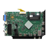
Detailed component layout and position information for the ZDS190R-6 chassis board.
Detailed component layout and position information for the ZDS190R-6 chassis board.
Detailed component layout and position information for the ZDS190R-6 chassis board.
Detailed component layout and position information for the ZDS190R-6 chassis board.
Detailed component layout and position information for the ZDS190R-6 chassis board.
Detailed component layout and position information for the ZDS190R-6 chassis board.
Detailed component layout and position information for the ZDS190R-6 chassis board.
Block circuit diagram for the power supply section, illustrating its main functional blocks.
Circuit diagram detailing the HDMI connections and associated components on the chassis board.
Circuit diagrams for SCART, VGA, CV, and YUV input/output sections and their components.
Circuit diagram for the Tuner and DVB-T2 module, including relevant components.
Circuit diagram illustrating the DVB-S tuner section and its associated components.
Circuit diagram for the USB interfaces, including USB 2.0 and USB 3.0 connections.
Circuit diagram related to the UHD processing section, showing key components.
Circuit diagrams for the Scaler/SOC and LAN interfaces, detailing their connectivity.
Circuit diagram illustrating the FLASH memory interface and its related components.
Circuit diagrams for the RAM modules, showing their connections and configurations.
Circuit diagram for the Frame Rate Control (FRC) module, detailing its components and connections.
Circuit diagram for the LVDS interface, crucial for display panel communication.
Circuit diagram for the keyboard interface, connecting to buttons or remote sensors.
Circuit diagrams for the audio amplifier sections, including speaker and headphone outputs.
Power supply schematic and component layout for the 4K module.
Circuit and component layout for the 4K module's processor and associated logic.
LVDS interface circuit and component layout for the 4K module.
RAM module schematics and component layout for the 4K module.
Component layout view of the DPS-103DP A and DPS-169CP A power supply boards.
Circuit diagram for the DPS-103DP A and DPS-169CP A power supply units.
Detailed circuit schematic for the DPS-103DP A and DPS-169CP A power supply units.
Component layout view of the DPS-110A power supply board.
Circuit diagram for the DPS-110A power supply unit.
Component layout view of the DPS-243AP power supply board.
Circuit diagram for the DPS-243AP power supply unit.
Component layout of the IR/LED board for VVA192R-1, showing component placement.
Component layout of the IR/LED board for VXM192R-3, showing component placement.
Component layout of the IR/LED board for ZCK192R, showing component placement.
Spare parts list categorized by chassis module, indicating part numbers and descriptions.
| Screen Size | 32 inches |
|---|---|
| Display Technology | LED |
| Smart TV | Yes |
| HDMI Ports | 3 |
| USB Ports | 2 |
| Energy Efficiency Class | A+ |
| HD Compatibility | Full HD |
| Built-in Wi-Fi | Yes |
| Sound Output | 20 W |
| Resolution | 1920 x 1080 pixels |