ENGLISH
14
OVERVIEW
--------------------------------------------------------------------------------------------------------------
Control buttons on the TV
Control elements
+V/P-
Turning the TV to standby
1 »8/I« Switches the television on and back
into standby mode.
Adjusting the volume or changing the
station
1 »V/P« Pre-selection for volume or channel
selection.
2 »–« Adjusts the volume;
Selects channels in s
teps.
3 »+« Adjusts the volume;
Selects channels in s
teps.
13
ENGLISH
OVERVIEW
--------------------------------------------------------------------------------------------------------------
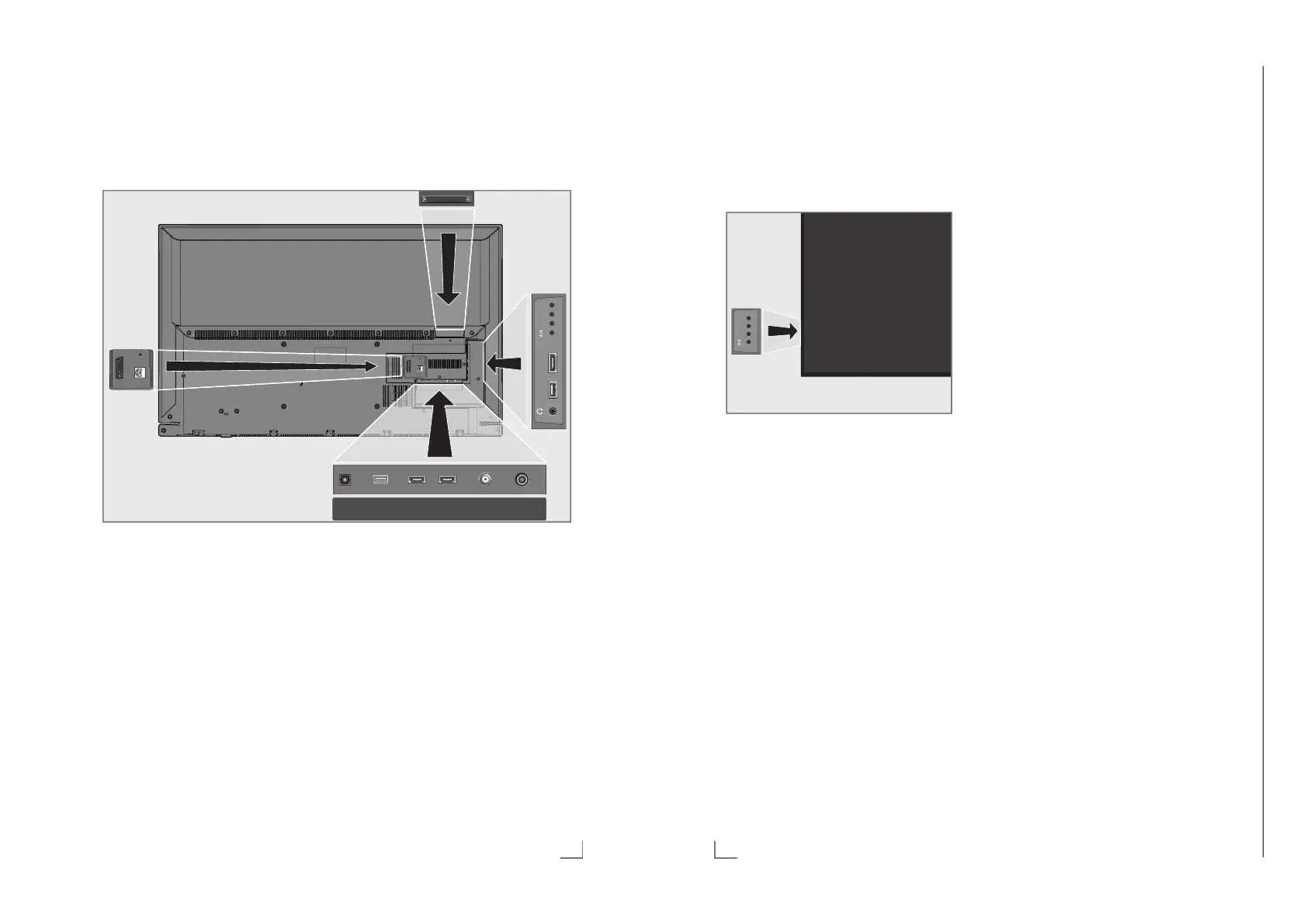
Connections on the television set
AV / S-VHS/COMPONENT
SERVICE
LAN
AV / S-VHS/COMPONENT
SERVICE
LAN
ANT-IN
5V
max.50mA
Optic Out SATELLITE
13/18V
max.500mA
HDMI2HDMI3(ARC)USB(HDD)
USB1 HDMI1 +V/P-
LAN Network cable connection
socket.
AV / S-VHS / COMPONENT
Euro/AV socket (CVBS
signal, RGB signal);
video signal input for
S-Video camera (with Scart-
S-VHS converter);
Video signal input (YUV sig-
nal with Scart-YUV converter).
SERVICE Service only.
Optic Out Audio output sockets (opti-
cal) for PCM/Dolby Digital
signals.
It is for digital multichannel
audio/video amplifier or
AV receiver connections.
USB(HDD) USB Harddisk socket for
external data medium and
PVR function;
connection for wireless
keyboard, mouse.
HDMI3 (ARC) HDMI socket, audio/video
signal input (HDMI).
HDMI2 HDMI socket, audio/video
signal input (HDMI).
SATELLITE Satellite antenna socket.
ANT-IN Antenna socket.
U Headphone connection
(3.5 mm jack);
external audio output (with
headphone-RCA con-
verter).
USB1 USB Harddisk socket for
external data medium and
PVR function;
connection for wireless
keyboard, mouse.
HDMI1 HDMI socket, audio/video
signal input (HDMI).
CI Common interface slot.
Operating Hints This chapter contains excerpts from the operating instructions. For further particulars please refer to the appropriate user instructions which can be downloaded by www.grundig.com, submenu Downloads/Manuals.
Chassis G5GRUNDIG Service
1 - 27
 Loading...