Do you have a question about the Grundig PA 5 and is the answer not in the manual?
Contact details for Grundig Service, including phone numbers for different departments.
Identifies the specific part number for the device.
Lists the necessary test equipment and measuring tools for service.
Provides detailed technical specifications for the device's performance.
Step-by-step guide on how to take the device apart for servicing.
Technical diagrams showing the electronic circuits and PCB layouts.
Lists of spare parts and visual exploded views for component identification.
Important notes regarding service procedures and safety.
Provides comprehensive technical specifications for the device.
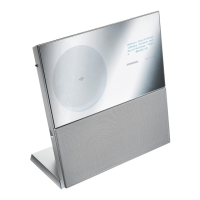
Instructions on how to set up and position the Turnit system.
General advice before starting disassembly procedures.
Specific steps for disassembling the control unit.
Detailed steps for removing the CD drive mechanism.
Detailed steps for removing the tape drive mechanism.
Instructions for removing the RF transmitter board.
Instructions for removing the power supply board.
Instructions for removing the main power board.
Instructions for removing the antenna board.
Instructions for removing the amplifier board.
Steps to remove the front and back panels of the unit.
Instructions for removing the tape audio circuit board.
Instructions for removing the tape logic circuit board.
Procedure for removing the main board and tuner board assembly.
Procedure for removing the power transformer.
Steps for disassembling the front panel.
Instructions for removing the input/output (I/O) board.
Steps for removing and disassembling the display drive.
Steps for removing the display mechanics.
Procedure for disassembling the display unit.
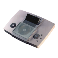
How to open the CD tray manually if the driver is defective.
Steps for removing the CD tray and printed circuit board.
Procedure for removing the CD player's pick-up unit.
Steps for removing toothed wheels and the tray driver assembly.
Steps for removing the cassette drawer.
Procedure for removing the tape drive mechanism.
Instructions for removing the tape deck's rotary head.
Steps for replacing the pressure roller levers.
Procedure for replacing the flywheels.
Instructions for removing the drive mechanism circuit board.
Detailed steps for adjusting the tape transport mechanism.
Steps for removing the amplifier unit.
Instructions for removing the top cover.
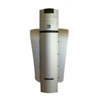
Procedure for removing the Kehler tube.
Steps for removing the subwoofer box.
Detailed steps for disassembling the subwoofer box.
Procedure for disassembling the Kehler tube.
Steps for removing the control board.
Instructions for removing the standby LED board.
Overview of operating instructions and where to find more information.
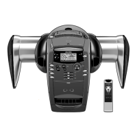
Explanation of the Space Fidelity surround sound technology.
Instructions for setting up the Turnit system components.
Adjusting display angle, brightness, volume, and muting.
Controlling Power Sound, Bass, Treble, and sound presets.
Instructions for tuning, station memory, and RDS features.
How to switch the system on/off and use standby mode.
Managing RF transmission and its settings.
Adjusting display settings and audio volume.
Details on Power Sound, Bass, Treble, and sound presets.
Tuning to stations, station search, and memory functions.
Searching radio stations by programme type and assigning names.
Instructions for selecting, inserting, and playing CDs.
Using playback modes like repeat, shuffle, and search functions.
Operating CD player with shuffle, repeat, and custom programmes.
Selecting tape sources, reverse modes, and playback types.
Using Dolby NR and basic cassette insertion/handling.
Using fast winding, music search, and end-of-tape features.
Protecting cassettes and performing recording operations.
Instructions for copying audio from CD to cassette.
Overview of operating the system and its features.
Technical explanation of the Space Fidelity sound system.
Instructions for setting up the Turnit system components.
Guidance for setting up units together or separately.
Instructions for setting up and using RF transmission.
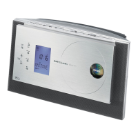
Overview of controls on the control unit and sound unit.
Functions related to the display and general remote operations.
Controls for sound adjustment and source selection via remote.
Operating modes and specific functions for tuner, tape, and CD.
Instructions for replacing the batteries in the remote control.
How to switch the system on/off and put it into standby.
Managing RF transmission and understanding multipath issues.
Adjusting volume, bass, treble, and sound presets.
Tuning to stations and selecting FM STEREO/MONO.
Using RDS features and adapting the antenna.
Procedures for automatic station search and manual tuning.
Storing, recalling, and deleting radio station memory locations.
Searching radio stations by programme type and assigning names.
Safety warnings and instructions for inserting and playing CDs.
Using playback modes like repeat, shuffle, and search functions.
Operating CD player with shuffle, repeat, and custom programmes.
Selecting tape sources, reverse modes, and playback types.
Using Dolby NR and basic cassette insertion/handling.
Using fast winding, music search, and end-of-tape features.
Protecting cassettes and performing recording operations.
Instructions for copying audio from CD to cassette.
Adjusting the IF filter and demodulator for optimal performance.
Adjusting station search, stereo crosstalk, and filters.
English guide for tuner adjustment procedures.
Guidance on replacing ceramic resonators in the tuner IF filter.
Adjusting tape speed, take-up torque, and wow/flutter.
Aligning the head gap and setting playback level.
Adjusting erase frequency and erase current.
Adjusting record blocking circuits and the MPX filter.
Setting frequency response and recording levels.
Adjusting head current and frequency during recording.
Adjusting bias voltage and distortion factor.
Adjusting tape speed, take-up torque, and wow and flutter.
Aligning the head gap and setting playback level.
Adjusting erase frequency and erase current.
Adjusting record blocking circuits and MPX filter.
Setting frequency response and recording levels.
Adjusting head current and frequency during recording.
Adjusting bias voltage and distortion factor.
Visual guide showing alignment points for the tape deck.
Overall block diagram illustrating the system's main components.
Information and notes on various electronic components.
Block diagram illustrating the control unit's internal structure.
Circuit diagrams for the main, I/O, and amplifier boards.
Circuit diagrams for main, headphone, and audio plug boards.
Detailed layout of components on the main board.
Circuit diagrams for multiple boards related to the control unit.
Circuit diagrams for power supply and related boards.
Circuit diagram for the cassette audio board.
Circuit diagrams for cassette logic, detector, and Dolby LED boards.
Circuit diagrams for tape logic, detector, and Dolby LED boards.
Circuit diagram for the CD player board.
Circuit diagram for the display unit.
Schematic diagram of the tuner section.
Circuit diagrams for the FM front end and stereo decoder.
Circuit diagram for the RDS demodulator.
Circuit diagrams for multiple unit boards.
Block diagram showing the sound unit's main functional blocks.
Circuit diagrams for RF receiver, audio plug, and LED boards.
Circuit diagrams for potentiometer, power, AC outlet, and filter boards.
Circuit diagrams for control, bass, and treble audio boards.
Diagrams showing control board and audio connection layouts.
Circuit diagrams for control, amplifier, and power switch boards.
Circuit diagrams for audio plug, potentiometer, and filter boards.
Circuit diagrams for LED and mute boards.
Detailed schematics for the audio amplifier boards.
Circuit diagrams for control, power switch, and audio plug boards.
Circuit diagrams for potentiometer, filter, and LED boards.
Circuit diagram for the CD player's pick-up unit.
Circuit diagram and pin connections for the display unit.
Internal circuit diagrams for key integrated circuits.
Visual exploded view of the control unit's components.
Detailed list of spare parts for the control unit.
Detailed list of spare parts for the sound unit.
Visual exploded view of the sound unit's components.
Detailed list of spare parts for the sound unit.
Visual exploded view of the CD drive mechanism.
Visual exploded view of the cassette tape drive mechanism.
List of spare parts for the CD drive mechanism.
List of spare parts for the cassette tape drive.
| Country | Germany |
|---|---|
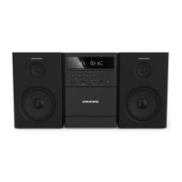
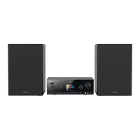
| Manufacturer / Brand | Grundig |
| Model | PA 5 |
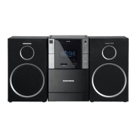
| Loudspeakers | 2 |
| Power Output | 5W |
| Shape | Bookshelf |
| Speaker Impedance | 4 Ohm |