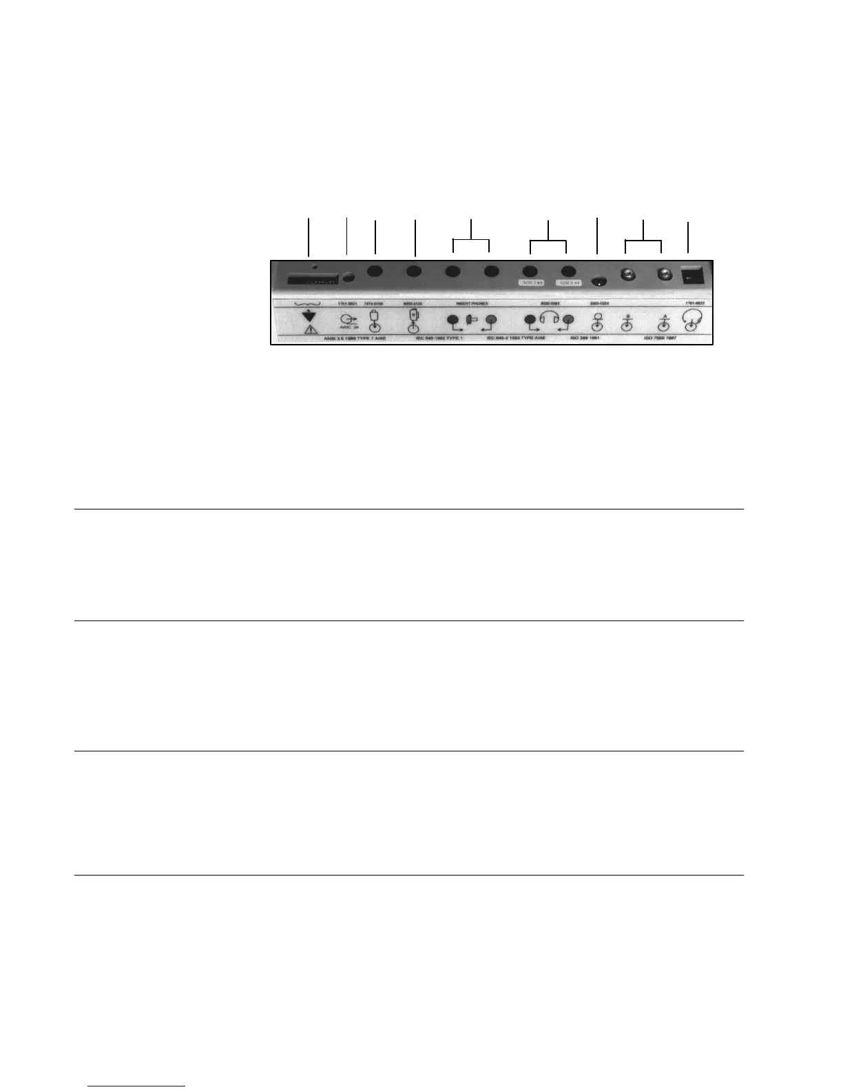
The connectors on the rear panel of the GSI 61 are shown in the following diagram.
The label and jacks are visible looking down onto the instrument, behind the LCD.
R9 R8 R7 R6 R5 R4 R3 R2 R1
(Modular Phone Jack)
Pin
Function
Output Voltage
Impedance
1
Mic High and +6 VDC 0.2 to 6.0 mV RMS 1.8 K ohm (output)
2
Phone Low GND 0 ohm
3
Phone High 3.0 mV to 1.0 V 300 ohm
4
Mic Shield GND 0 ohm
(RCA plug)
Input jacks for optional stereo tape cassette or CD player.
Voltage range required: 0.2 to 1.0 V to obtain 0 VU
Input Impedance: 15 K ohm
(3.5 mm stereo jack)
Position
Function
Output Voltage
Impedance
1 Tip Mic High 0.2 to 2.0 mV RMS and +6V AC 10 K ohm
2 Ring Mic Low - - - - - - - - - -
3 Shield Chassis Ground - - - - - - - - - -
(1/4 inch stereo jack)
Stereo phone jacks for left (blue) and right (red) earphones, patch cords, or High
Frequency earphone connector cords.
Voltage: 1µV to 7.0 V RMS (4.45 V RMS for High Frequency)
Output impedance: 5 ohms or less
(1/4 inch monaural jack)
Grason-Stadler GSI
61 CLINICAL AUDIOMETER
Connectors, Controls and Indicators
Rear Panel
R1 - Monitor
Headset
R2 - Ext A and Ext
B
R3 - Talkback
Microphone
R4 - Left and Right
Ear
Phone Outputs
R5 - Left and Right
2-2
1761-0100 Rev. B