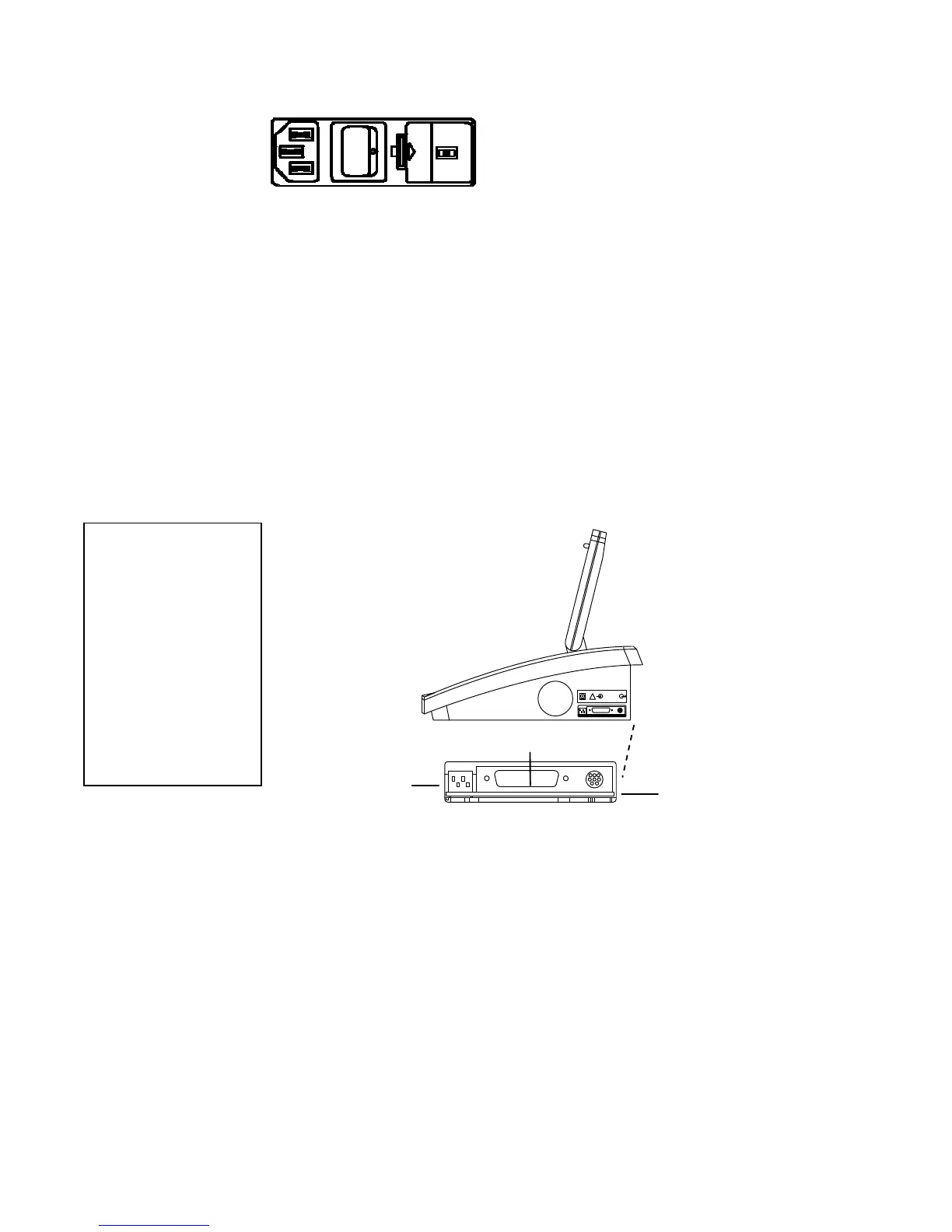
The connectors on the left side panel are shown below.
The power entry module is composed of the power
switch, fuse drawer and voltage selection switch,
and power cord with hospital grade plug appropriate
for the country of destination.
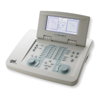
When turned ON, the GSI 61 automatically initializes and displays a screen which
states the type of audiometer (IEC and ANSI specified for speech audiometry)
followed by a status screen. With the status display, the GSI 61 is brought to the
initialization state.
The frequency is set at 1000 Hz and:
Channel 1 Channel 2
Steady tone NB Noise
Phone-Right Phone-Left
0 dB HL -10 dB HL
Serial Port
This instrument has Remote and Printing capability, or the following connectors will be
visible on the right side panel of the GSI61:
Remote/Printer Option
RS 232 Remote Port
A mini-DIN connector uses a standard Apple “Hayes Modem” cable (supplied) to
provide serial connection to the equipment.
USB Remote Port
A Standard A/B USB cable provides connection to a PC.
Printe
Port
A 25-pin PC-Printer Interface Connector. Connects to the printer via a standard PC-
parallel printer cable.
USB Printer Port
A Standard USB cable provides connection to a printer. See Chapter 6 for more
DIP Switches
For more detail on these DIP switch settings, and attaching and using a printer, refer to
the Optional Accessories section beginning on page 2-18.
Grason-Stadler GSI
61 CLINICAL AUDIOMETER
!
Printer Port
Dip Switches
Left Side
Panel
Right Side
Panel
2-4
RS232
Remote Port
Please Note:
Depending on the
date product
configuration
purchased, the GSI 61
is either equipped
with a Serial Port, a
USB Port, or no
Remote port at all.
1761-0100 Rev. B
 Loading...