EasyManua.ls Logo

GTO FM139 User Manual

GTO FM139
12 pages
To Next Page IconTo Next Page
Page #1 background imageLoading...
Page #1 background image
GTO, Inc. • 3121 Hartsfield Road • Tallahassee, Florida 32303
1-800-543-GATE (4283) • Technical Support 1-800-543-1236
www.gtopro.com
When an EXIT WAND is in use, the automatic gate opener could be activated by a
child on a bicycle, tricycle or other metal play equipment. This product is not recom-
mended for applications exposed to children.
WARNING
WARNING
!
WAND with 50, 100 or 150 feet
of Direct Burial Cable
Range
Adjustment Board
Warning Signs (2)
Wire Nuts (3)
Battery Connection
Wires (2)
Double Spade
Connectors (2)
Ty-Wraps (4)
Wire Clamp
!
WARNING
GATE OPENING
SENSOR IN USE
The Automatic Gate Opener is activated when a
vehicle comes within range of the sensor buried
along side the driveway and could possibly be
activated by a child on a bicycle, tricycle or other
metal play equipment.
Parts Identification:
WARNING
RWINSTMM
rev-5/18/07
EXIT WAND
Installation Manual

Other manuals for GTO FM139

Question and Answer IconNeed help?

Do you have a question about the GTO FM139 and is the answer not in the manual?

GTO FM139 Specifications

General IconGeneral
BrandGTO
ModelFM139
CategoryAccessories
LanguageEnglish

Summary

Parts Identification

Before You Start

Terms and Definitions

Defines key terms and concepts related to the EXIT WAND operation and installation.

How the EXIT WAND Works

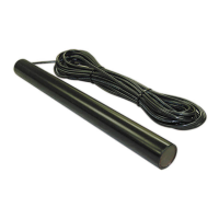
Explains the principle of operation for the EXIT WAND, detailing how it detects metal objects.

EXIT WAND Range Adjustment

Details how the range adjustment potentiometer (POT) on the control board affects sensitivity.

WAND Placement

Provides guidance on selecting the optimal location for burying the WAND for best performance.

Installation Overview

Installing the Exit Wand

Determining WAND Location

Details how to determine the optimum location for the EXIT WAND, including digging instructions.

Installing the Wire Clamp

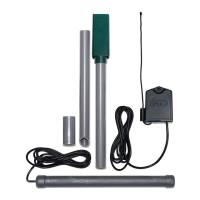
Step-by-step instructions for installing the WIRE CLAMP to secure the WAND cable into the control box.

Wiring the WAND to GTO/PRO Gate Openers

Connecting the Range Adjustment Control Board

Power Supply Connection

Connects the RED and BLACK control board wires from the opener to the DOUBLE SPADE CONNECTORS.

Powering Up the WAND

Adjusting the Range

Instructions on how to test the WAND and adjust the range potentiometer for optimum performance.

Safety Precautions

Instructions to place WARNING SIGNS on both sides of the gate using the included Ty-wraps.

Installation on Other Brand Gate Openers

Typical Gate Wiring Connection

Provides reference leads and definitions for connecting the WAND to non-GTO/PRO gate openers.

Power Supply Connection (Other Brands)

Details DC and AC power supply connections for gate openers from other manufacturers.

Relay Output Connection (Other Brands)

Explains how to connect the WAND's BLUE and BLACK wires to the 'FREE EXIT/ENTRY' and 'COMMON/GND' terminals.

Range (POT) Board Connection (Other Brands)

Guides connection of the YELLOW wire from the WAND and BLACK wire from the Range Adjustment Board.

Technical Specifications

Troubleshooting

Other GTO Products

Related product manuals