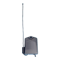
RB709-U
Relay Output Universal Receiver
Owners Manual
The RB709-U digital receiver is a
wireless radio control designed for
use with automated gate openers
and garage door openers. The
receiver has two channels for re-
ceiving signals from two separate
transmitters.
www.gtoinc.com
Specifications
Compatible transmitter:
•GTOnarrowbandtransmitters(318MHz)
Power input:
•8-24Vac/dc,10mastandby,40maactivated(Red&Blackwires).
Outputs:2channelspulsedoutputs
•2channelsdry-contactnormallyopenrelayoutputs.
•Channel1:Blue&Greenwires.
•Channel2:Yellow&Brownwires.
•Activatedfor.5secondswhenthecorrecttransmittercodeisreceived.
•Relayswitchingmaximumrating:24Vac/dc@1A.
•OperatingRange50to100feet(15.2to30.5m)
Indoor/Outdoorcompatible.
Mounting the Receiver Connect Receiver to Relay Inputs and Power
Consider the following when mounting the receiver:
•Standardreceivercablelengthis10feet(3.05m).
•Forexteriorapplicationsrunthecablethrough
PVCconduittoprotectitfromdamage.
•DONOTruncableinconduitcontainingacwiring.
•Thereceiverrangecanvaryfrom50to100
feet(15.2to30.5m)dependinguponweather,
topography,andexternalinterference.
FCC Regulation
This device complies with FCC rules Part 15. Operation is subject to the following conditions:
1. This device may not cause harmful interference.
2. This device must accept an interference that may cause undesired operation.
Transmitter distance may vary due to circumstances beyond our control. NOTE: The manufacturer
is not responsible for any radio or TV interference caused by unauthorized modifications to this
equipment. Such modifications could void the user’s authority to operate the equipment.
NOTE: Do not mount upside down in exterior applications.
Channel 1 (GREEN WIRE to COM)
Channel 1 (BLUE WIRE to RELAY)
Channel 2 (BROWN WIRE to COM)
Channel 2 (YELLOW WIRE to RELAY)
2nd GATE OPERATOR or DOOR OPENER
1st GATE OPERATOR or DOOR OPENER
8 to 24 VOLT AC/DC
POWER SUPPLY
RED WIRE to POSITIVE
BLACK WIRE to NEGATIVE
RED
BLACK
GREEN
BLUE
BROWN
YELLOW