5.2
4
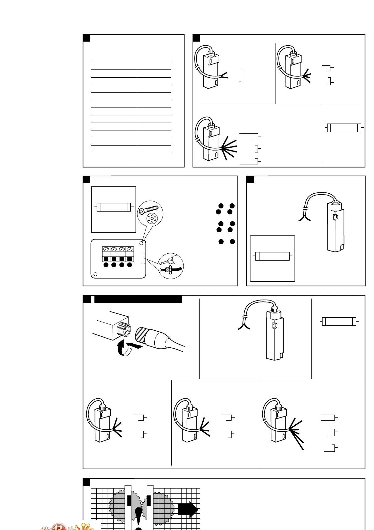
(x) Ferrogard external fuse rating
(safety contacts)
5.1
Ferrogard 1, 2, 20, 21, GS1 & GS2
5.3
5.4 (s1) OPTIONAL PLUG-IN CONNECTOR
(x) Nennwerte der externen
Sicherung (Öffnerkontakt)
Table des fusibles externes Ferrogard
(y) Ferrogard Typ /
Type Ferrogard
(z) Externe Sicherung (flink)
Fusible externe ultra-rapide
(a1) Braun /
Marron
(b1) Blau /
Bleu
(c1) Öffner (Sicherung extern)
Sécurité (fusible externe)
(d1) 1 Öffner /
1N/C (contact de sécurité)
(e1) Schwarz /
noir
(f1) Weiß /
Blanc
(g1) 1 Schließer /
1N/O contacts auxiliaires
(h1) Rot /
Rouge
(i1) Schließer /
auxiliaire
(j1) Grün /
Vert
(k1) Gelb /
jaune
(m1) Öffner (nur 21) (Sicherung extern)
Sécurité (21 seulement) (fusible externe)
(n1) 1 Öffner (Hilfsk.)
1N/C contacts auxiliaires = 3+4
(p1) Sicherung (flink) /
Fusible ultra rapide
(q1) Jeden Sicherheitskreis extern
absichern (siehe Schritt 4)
Chaque contact de sécurité doit être équipé
d’un fusible de protection externe (voir étape 4)
(r1) Anschlüsse /
Connexions
(s1) Wahlweise mit Steckverbinder
Connecteur à fiche supplementaire
(t1) Rot+Blau /
Rouge+Bleu
(u1) Rot /
Rouge
(v1) Rot+Schwarz /
Rouge+Noir
(w1) Rot+Weiß /
Rouge+Blanc
(x1) Rot+Gelb /
Rouge+Jaune
(y1) Grün /
Vert
(y) Ferrogard type (z) External quick
blow fuse
FRS 1 ≤ 1.6A
FRS 2 ≤ 1.6A
FRS 3 ≤ 1.6A
FRS 4 ≤ 1.6A
FRS 5 ≤ 1.6A
FRS 6 ≤ 1.6A
FRS 9 ≤ 800mA
FRS 10 ≤ 2.5A
FRS 20DC ≤ 800mA
FRS 21AC ≤ 1.6A
FRS 21DC ≤ 800mA
GS1 ≤ 1.6A
GS2 ≤ 1.6A
Ferrogard 3, 4 & 5 Ferrogard 6, 9 & 10
Ferrogard 1 (FRS 1) GS1 & GS2
(d1) 1 N/C (Safety Contacts)
Ferrogard 20 (FRS 20)
(d1) 2 N/C (Safety Contacts)
Ferrogard 2 (FRS 2)
(d1) 1 N/C (Safety Contacts)
(g1) 1 N/O (Aux Contacts)
Ferrogard 21 (FRS 21)
(d1) 2 N/C (Safety Contacts)
(g1) 1 N/O (Aux Contacts)
(p1) Quick Blow
(q1) Fuse each safety
circuit externally
(see Step 4)
(a1) Brown
(b1) Blue
(b1) Blue
(c1) Safety (fuse externally)
(i1) Auxiliary
(m1) Safety (21 only) (fuse externally)
(e1) Black
(f1) White
(j1) Green
(k1) Yellow
(h1) Red
IMPORTANT
/ WICHTIG
(p1) Quick Blow
(q1) Fuse each safety
circuit externally
(see Step 4)
IMPORTANT
/ WICHTIG
(b1) Blue
(c1) Safety
(fuse externally)
(a1) Brown
(c1) Safety
(fuse externally)
(c1) Safety
(fuse externally)
(e1) Black
(f1) White
Ferrogard 2 (FRS 2)
(d1) 1 N/C (Safety Contacts)
(g1) 1 N/O (Aux Contacts)
(p1) Quick Blow
(q1) Fuse each safety
circuit externally
(see Step 4)
(b1) Blue
(c1) Safety
(fuse externally)
(i1) Auxiliary
(e1) Black
(f1) White
(a1) Brown
IMPORTANT
/ WICHTIG
Ferrogard 20 (FRS 20)
(d1) 2 N/C (Safety Contacts)
(b1) Blue
(c1) Safety
(fuse externally)
(c1) Safety
(fuse externally)
(e1) Black
(f1) White
(a1) Brown
Ferrogard 21 (FRS 21)
(d1) 2 N/C (Safety Contacts)
(g1) 1 N/O (Aux Contacts)
(u1) Red
(c1) Safety
(fuse externally)
(c1) Safety
(fuse externally)
(v1) Red+Black
(w1) Red+White
(t1) Red+Blue
(i1) Auxiliary
(x1) Red+Yellow
(y1) Green
(r1) Connection Details
Ferrogard 3 (FRS 3)
(d1) 1 N/C Safety Contacts = 1 & 2
(n1) 1 N/C Aux. Contacts = 3 & 4
Ferrogard 4 (FRS 4)
(d1) 1 N/C Safety Contacts = 1 & 2
(g1) 1 N/O Aux. Contacts = 3 & 4
Ferrogard 5 (FRS 5)
(d1) 1 N/C Safety Contacts = 1 & 2
1234
(p1) Quick Blow
(q1) Fuse each safety
circuit externally
(see Step 4)
IMPORTANT
/ WICHTIG
(d1) 1 N/C Safety Contacts
(b1) Blue
(a1) Brown
Ferrogard 6 & 9 (FRS 6 & FRS 9)
(d1) 1 N/C Safety Contacts
(b1) Blue
(a1) Brown
6
After installation check all of the interlocked doors to ensure that
the machine is isolated and stopped whenever the guard is not closed.
Nach der Montage an allen Schutztüren prüfen, ob die Maschine
beim Öffnen der Schutztür abgeschaltet wird.
Après installation, manoeuvrez chaque porte pour vous assurer de
l'arrêt de la machine tant que chaque protecteur n'est pas fermé.
 Loading...