6. INSTALLATION, START and LOAD
Although the choice of the genset place changes according to the business locaon, the following points
must be taken into account.
1. The place must be dry, free from dust, airy and bright eld.
2. Fuelling
3. The structure of the surface
4. The availability of access and exit to the place
5. Proper air entrance
6. Proper exhaust exit
7. Proper warm air exit
8. Noise level
9. Stac grounding
Assembly:
Failing that the assembly is not done by our rm or our authorized technical service, the product will not be
covered by the guarantee anymore. If the assembly will be done by your rm, follow the instrucons below.
In order to get the required performance, the connecon between the generator set and the facility
must be done properly. The proper connecon is shown in the Figure 6.2. There are two cables that are
connected to the panel. One is for the control of the mains entrance, and the other one is the generator
exit. The main which is taken from the counter or compensaon panel is transferred to the receiver by the
contactor. The important point is that the generator is connected to the load aer the counter.
The place of the generator must be suitable for mounng and dis-
mounng operaons of the genset without any me loss. Clear up
the place for comfortable entrance and exit.
In case the generator set may need to be dismounted in the future,
do not change the liing hooks on the generator.
The fuel pump, injectors and the lters must be in a reachable point
for easy replacement.
If there is a mark on the ywheel for the adjustment of the m-
ing-gear, make it seeable.
Cylinder heads, rocker cover and valve mechanism must be dis-
mountable without demounng other parts.
Oil ller cap, oil drain tap and oil level gauge must be in a reachable
point.
Water ller cap and drain tap must be in a reachable point.
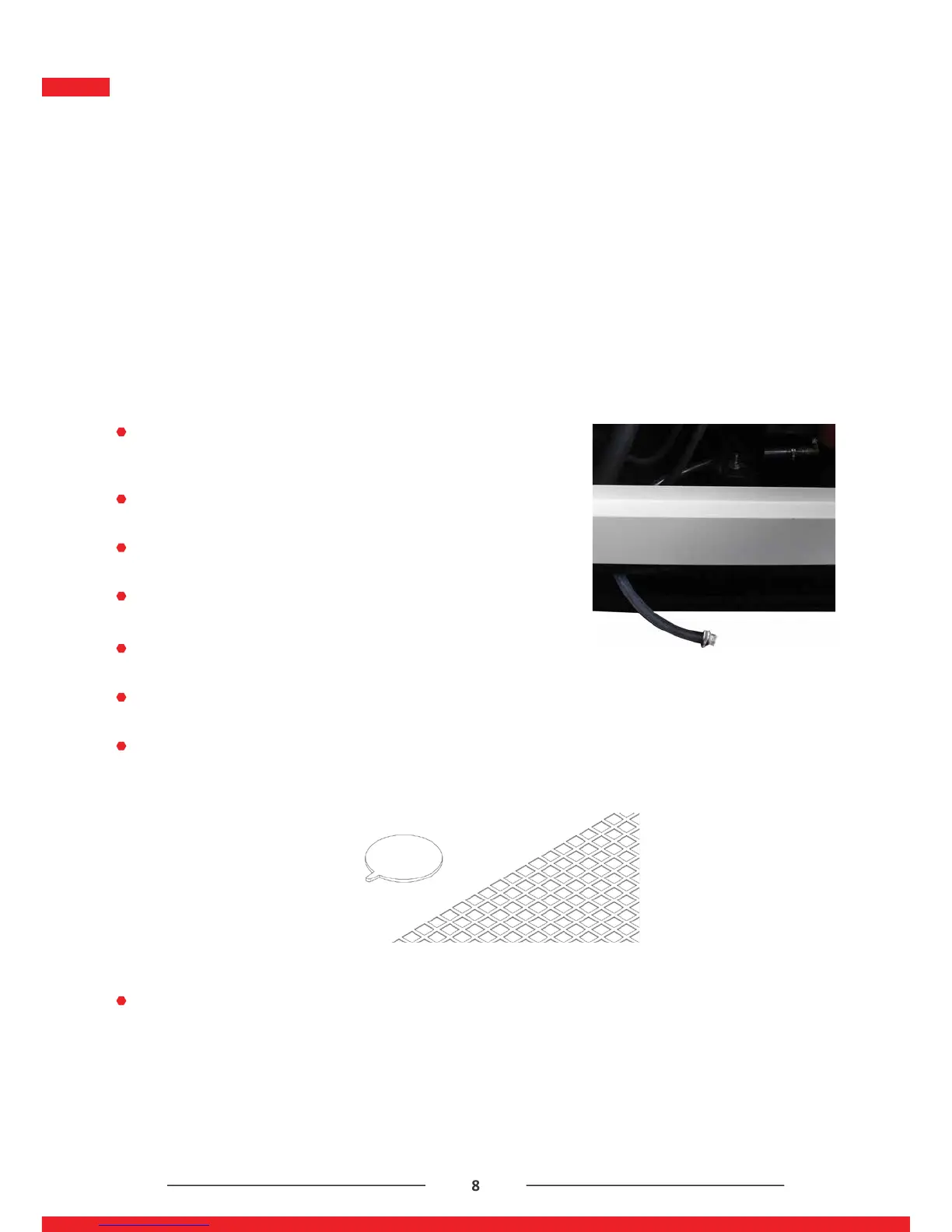
Figure 6.2 : Water Filling Cover
Figure 6.2 : Oil Drain Plug



 To Next Page