Do you have a question about the Guideline Geo ABEM Terrameter LS 2 and is the answer not in the manual?
Steps for setting up the survey line, placing electrodes, and laying out cables for resistivity measurements.
Instructions on connecting cables, power, and safely initiating the instrument for operation.
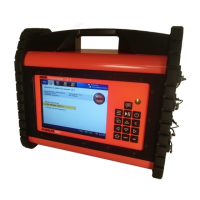
Overview of the instrument's screen layout, navigation menu, tabs, view, and status bar elements.
Explanation of how to use the instrument's keypad and its mapping to functions for navigation and operation.
Guide to creating new projects and tasks, including setting up survey parameters like spread and electrode spacing.
Configuration options for the receiver, including measure mode, stacking, error limits, and acquisition times.
Configuration options for the transmitter, covering current/voltage limits, electrode testing, and load variation.
Steps to configure measurement settings, including cable setup and initiating the measurement process safely.
Procedure for testing electrode contact resistance before starting measurements and troubleshooting failures.
How to monitor real-time measurement progress, view results, and interpret status bar information.
Instructions for downloading project data from the instrument to a USB storage device.
Instructions for downloading specific tasks from the instrument to a USB storage device.
The ABEM Terrameter LS 2 is an electrical resistivity instrument designed for geophysical surveys, primarily for 4-cable 48 and 64 electrode systems. Its core function is to measure electrical resistivity and induced polarization (IP) of the ground, providing insights into subsurface geological structures.
The instrument operates by transmitting current into the ground through electrodes and measuring the resulting voltage differences, which are then used to calculate resistivity and IP. It supports various measurement modes, including pure resistivity (Res), resistivity and traditional 50% duty cycle IP (Res, IP), and novel 100% duty cycle IP (IP 100%). The system is designed to handle multiple electrodes, allowing for efficient data acquisition over survey lines. It features a relay matrix that exercises during startup, indicating its readiness for operation. The device can record full waveform data, capturing the complete output and input current and voltage patterns during the measurement cycle, which can be valuable for detailed analysis, though it results in larger project files. It also includes an electrode contact test function to ensure proper electrode grounding and connection before measurements begin, which is crucial for data quality. The instrument provides real-time monitoring of measurement progress, displaying parameters such as channel number, electrode pairings, measured quantities (voltage or current), standard deviation, resistance, apparent resistivity, and chargeability.
The ABEM Terrameter LS 2 is designed for field use, with a layout procedure that involves setting up a straight survey line, hammering electrodes vertically into the ground, and aligning cable take-outs with electrodes. It supports both 48 and 64 electrode systems, requiring the use of up to four survey cables. The instrument is typically placed in the middle of the survey line, between Cable 2 and Cable 3, along with an external 12V car battery for power. Cable joints are directional, with ridges indicating the direction towards the instrument, ensuring correct connection. Jumper wires are used to connect cable take-outs to electrodes.
The user interface includes a navigation menu with options for Projects, Settings, Measure, and Instrument, each with corresponding tabs. The 'Welcome View' displays recent activities and instrument information. Users can create new projects and tasks, defining the spread (e.g., 4x12 for 48 electrodes or 4x16 for 64 electrodes) and protocol (electrode array). Minimum electrode spacing can be set via a virtual keyboard.
Receiver settings allow users to select the desired measurement mode, define stacking and error limits to improve data quality, and set delay and acquisition times to optimize noise reduction and IP effect avoidance. IP windows rely on pre-loaded settings. The power line frequency can be selected based on the survey region (50Hz or 60Hz), and the sample rate for full waveform recording can be defined.
Transmitter settings include minimum and maximum current, power, and voltage limits, which provide warnings if actual values fall below thresholds. The 'Electrode Test' feature, typically set to 'Focus One', tests contact resistance and connection of each electrode. Users can define 'Bad' and 'Fail' electrode thresholds. Load variation margin can be set to maintain constant current during measurements.
During measurements, the 'Progress' view monitors real-time data. The instrument provides warnings for high standard deviations, excessive negative IP values, or error messages. The measurement progress is indicated by the number of completed measurements relative to the total. The emergency stop button is a critical safety feature that must be engaged when handling cables and electrodes and disengaged to start measurements. If an electrode test fails, the instrument provides feedback on which electrodes are 'Bad', 'Fail', or 'No Contact', prompting the user to troubleshoot by checking jumper wires, electrode grounding, or repositioning. Individual electrodes or entire cables can be excluded or forced into use if necessary.
The manual emphasizes the importance of keeping connectors dry and clean, as poor handling and maintenance are the primary causes of cable failure. Dust caps should always be interconnected during measurements to maintain cleanliness and dryness. The instrument's robust design is intended for field conditions, but proper care of cables and connectors is highlighted as essential for longevity and reliable operation.
For data management, the ABEM Terrameter LS 2 supports downloading data via a USB storage device or through PC companion software, ABEM Terrameter LS Toolbox, using an Ethernet or Wi-Fi connection. Projects and tasks can be exported from the instrument to a USB device, with the project database file being crucial for opening data in the Toolbox for quality assurance and filtering. The system also includes notification icons for battery status (external and internal), GPS status, and time of day, which can aid in monitoring the instrument's operational health. The emergency stop button serves as a critical safety and maintenance feature, preventing current and voltage transmission during handling of potentially life-threatening components.
| Operating Temperature Range | -20°C to +50°C |
|---|---|
| Transmitter | Built-in |
| Current Output | 2.5 A |
| Input Impedance | 10 MΩ |
| Battery Life | 10 hours |
| Measurement Principle | Induced Polarization (IP) |
| Category | Geophysical Instrument |
| Data Storage Capacity | Internal storage, SD card slot |
| Power Supply | Rechargeable battery |
| Voltage accuracy | 0.5% |
| Current accuracy | 0.5% |