(3) The car should be thoroughly warm before the tests begin. It is not enough to
leave the car to warm while parked. The car should be taken for a drive, and the tests not
commenced until water temperature, engine, and exhaust system are thoroughly
heated, and are at normal running temperature.
(4) Study the workshop manual for the particular car (or consult the information
given later in this booklet) to identify the correct adjustment screws that control the
mixture strength and the idle speed. Identify the direction to turn the screws to achieve
the desired effect
(i.e. mixture richer or weaker, idle speed faster or slower). Make a note
of the initial position of the adjustments before commencing work, so that in case of
difficulty, or of the wrong adjustment is changed, the setting can be restored to its
original position.
(5) Have to hand the correct tools for making the necessary adjustments
(e.g.
screwdriver or allen key). If the manual quotes a CO level at a particular engine speed,
then the user needs to provide a tachometer (Gunson's Testune and Autoranger
incorporate a tachometer suitable for this purpose).
5. INSTRUCTIONS FOR USE
(1) Ensure that the car is thoroughly warm as mentioned above, that it is parked in
the open air, with the handbrake applied, and with the engine running.
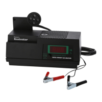
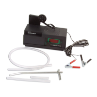
(2) Place the assembled Gastester on aconvenient flat surface close to the vehicle's
exhaust pipe outlet. Connect the red and black clips to the vehicle's battery (red to
+,
black to
-).
Only a 12 volt battery must be used. If thevehicle has a 6v or 24v banery, then
an external battery must be used, such as the battery of a nearby car. The current draw of
the unit is quite high
(1
A), and so a good battery should be used. DO NOT INSERT THE
EXHAUST PROBE INTO THE EXHAUST PlPE AT THlS STAGE.
(3)
Press the function check switch on the instrument to make sure that the pointer
moves into the circuit check box on the right of the meter scale, otherwise check the
connections. Return the switch to its normal operating position. DO NOT INSERT THE
EXHAUST PROBE INTO THE EXHAUST PlPE AT THlS STAGE.
(4)
Wait at least
8
minutes for the instrument to thoroughly warm up. Keep the car
engine running. DO NOT INSERT THE EXHAUST PROBE
INTO THE EXHAUST PlPE
AT THlS STAGE.
(5) Use the rotary calibration control to carefully set the pointer to the CALIBRATE
position marked on the meter scale. The CAI-IBRATE position can be found near the 2%
marking on the scale. Having set the pointer to the CALIBRATE position, do not further
adjust the calibration control for the subsequent tests. (NB. The CALIBRATE position
represents what theinstrument should registerwhen the probe is in air. It iscoincidental
that air should measure the same as exhaust gas with 2% CO. When the probe is
subsequently inserted into the exhaust pipe, the pointer of the instrument may move
down or up from the CALIBRATE position, depending on whether the exhaust has less
than, or more than, 2% CO).
(6)
Ensure that the engine is set to idle speed, or to the RPM stated by the
manufacturer if this is specified. NOW INSERT THE PROBE INTO THE VEHICLE
EXHAUST PIPE, to a minimum of 3/4 of its length,
i.e.
8"
or 20cm. In order for the
automatic water drain to
furTction,.the probe pipe should fall continuously from the
exhaust end to the pump end to allow water droplets to run down. Otherwise the water
will collect at the lowest point and will have to be drained manually.
 Loading...