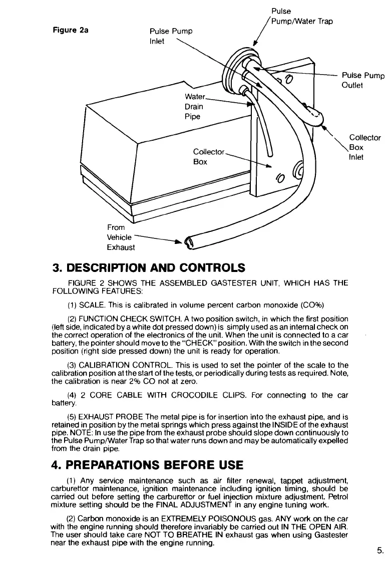
Figure
2a
Pulse
/~ump/Water Trap
Pulse Pump
lnlet
\
-i
Water-
Drain
I
\
Pi~e
Vehicle
Exhaust
Pulse Pump
Outlet
Collector
\BOX
Inlet
3.
DESCRIPTION AND CONTROLS
FIGURE 2 SHOWS THE ASSEMBLED GASTESTER UNIT, WHICH HAS THE
FOLLOWING FEATURES:
(1) SCALE. This is calibrated in volume percent carbon monoxide
(CO%)
(2) FUNCTION CHECK SWITCH. A two position switch, in which the first position
(lefl side, indicated by a white dot pressed down) is simply used as an internal check on
the correct operation of the electronics of the unit. When the unit is connected to a car
battery, the pointer should move to the "CHECK position. With the switch in the second
position (right side pressed down) the unit is ready for operation.
(3)
CALIBRATION CONTROL. This is used to set the pointer of the scale to the
calibration position at
thestart of the tests, or periodically during tests as required. Note,
the calibration is near 2% CO not at zero.
(4)
2 CORE CABLE WITH CROCODILE CLIPS. For connecting to the car
battery.
(5)
EXHAUST PROBE The metal pipe is for insertion into the exhaust pipe, and is
retained in position by the metal springs which press against the INSIDE of the exhaust
pipe. NOTE: In use the pipe from the exhaust probe should slope down continuously to
the Pulse
Pump/Water Trap so that water runs down and may
be
automatically expelled
from the drain pipe.
4.
PREPARATIONS BEFORE USE
(1) Any service maintenance such as air filter renewal, tappet adjustment,
carburettor maintenance, ignition maintenance including ignition timing, should be
carried out before setting the carburettor or fuel injection mixture adjustment. Petrol
mixture setting should
be
the FINAL ADJUSTMENT in any engine tuning work.
(2) Carbon monoxide is an EXTREMELY POISONOUS gas. ANY work on the car
with the engine running should therefore invariably be carried out IN THE OPEN AIR.
The user should take care NOT TO BREATHE IN exhaust gas when using Gastester
near the exhaust pipe with the engine running.
5.
 Loading...