Guide to the Appliance
2
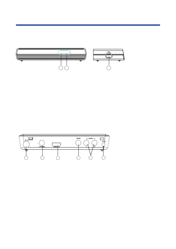
1. STANDBY INDICATOR: Used to visually show power state of the set top box,
the green LED will be light if turned on the set top box and the red LED will be
light if the set top box entered standby mode.
2. REMOTE CONTROL SENSOR: Used to receive the signal from the remote
control.
3. USB JACK(Optional): Used to connect to an external USB 2.0 device.
Note: Not all receivers have the USB Jack.
2 3
1
Front panel
1 2
3
4 5 6
1. RF IN: This socket allows you to connect your external aerial.
2. COAXIAL: This socket allows you to connect the Set Top Box to a compatible
surround sound system.
3. HDMI OUT: This socket allows you to use your HDMI cable for a premium
high definition connection.
4. VIDEO: This socket allows you to connect your Set Top Box via Composite
Video Signal.
5. AUDIO L/R: This socket allows you to connect your Set Top Box to receive the
Audio L/R signal.
6. POWER INPUT: This socket is where you connect your main power to the unit.
Rear panel
 Loading...