Do you have a question about the GW Instek GFC-8131H and is the answer not in the manual?
Instructions for unpacking and inspecting the instrument for damages during transportation.
Guidance on checking and selecting the correct line voltage and fuses for the instrument.
Ensuring proper ventilation and adherence to specifications for safe and effective equipment operation.
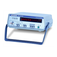
Controls for input selection, coupling, attenuation, low pass filter, frequency, and period modes for channels A and B.
Controls for power, reset, gate time adjustment, and trigger level settings for measurement operations.
Indicators for measurement units (Hz, S), exponents, display status, and overflow conditions.
Measure frequency from 0.01Hz-120MHz (Ch A) and 50MHz-1.3(2.7)GHz (Ch B), and period for Ch A.
Adjustable gate time (10ms-10s or 1 period) affects sampling rate and resolution. Knob controls update speed or freeze display.
Adjust trigger voltage for Ch A input signal (±2.5V×ATT); knob can function as auto-trigger.
Procedures for calibrating input offset voltage, standard oscillator, and hysteresis bias voltage.
Instructions for cleaning the instrument using mild detergent and water, avoiding harsh chemicals.
| Type | Function Generator |
|---|---|
| Data Hold | Yes |
| Output Impedance | 50 Ω |
| Current Measurement Range | Not applicable |
| Resistance Measurement Range | Not applicable |
| Display | LCD |
| Battery | Not applicable |
| Waveforms | Sine, Square, Triangle, Pulse |
| Modulation | AM, FM |
| Sweep | Linear, Logarithmic |
| Trigger | Internal, External |
| Power Supply | AC 100-240V |