EasyManua.ls Logo

GYROZEN 1580R - User Manual

GYROZEN 1580R
40 pages
Print Icon
To Next Page IconTo Next Page
Loading...
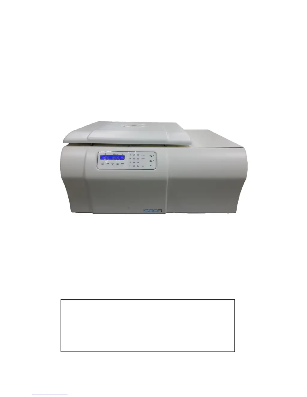
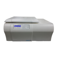
Refrigerated, Multi-purpose, High speed Centrifuge, 1580R – Service manual
1
1. Model: Refrigerated, Multi-purpose, High speed Centrifuge, 1580R
2. Manufacturer: Gyrozen Co., Ltd.
3. Service: BMS Co., Ltd. Technical Service Team, 82- 2-3471-8171
Gyrozen Co., Ltd Customer Service Team, 82-70-8620-5350

Questions and Answers

  • H
    Howard WalkerSep 23, 2025
    How to fix Door PhotoSensor error (Motor open & Door In)(2) in GYROZEN 1580R?
    • M
      Molly DavisSep 23, 2025
      To address a Door PhotoSensor error (Motor open & Door In)(2) on your GYROZEN Laboratory Equipment, replace the defective or damaged photo sensor with a normal one.
  • B
    Bonnie ButlerAug 23, 2025
    What to do if GYROZEN 1580R Laboratory Equipment has no display or power?
    • W
      wlewisAug 23, 2025
      If your GYROZEN Laboratory Equipment has no display or power, first, ensure the power cord is correctly plugged into an appropriate and secure power outlet. If the issue persists, try turning the power switch off and then resetting the device.
  • G
    Greg SullivanAug 25, 2025
    How to troubleshoot a door that won't open or close on GYROZEN 1580R?
    • R
      Rita WilliamsAug 26, 2025
      If the door of your GYROZEN Laboratory Equipment does not open or close properly, start by detaching the front panel to check the cause of the issue. You may need to adjust the position of the door lock or replace it.
  • L
    Lindsay MurphyAug 27, 2025
    What to do if the motor overheats in GYROZEN 1580R Laboratory Equipment?
    • R
      Rebecca AdamsAug 27, 2025
      If the motor of your GYROZEN Laboratory Equipment overheats (internal temperature exceeds 110?), turn off the power switch and allow the motor to cool down for about 1 hour with the door open. After cooling, test again to see if the problem remains. If it does, the motor may need to be replaced.
  • J
    Joseph WardAug 27, 2025
    Why won't the rotor rotate in my GYROZEN Laboratory Equipment?
    • A
      Alexander EatonAug 27, 2025
      If your GYROZEN Laboratory Equipment's rotor doesn't rotate and the operation cannot start, perform the corrective action as listed in E1 and/or E9. Also, make sure to press down the door firmly until the latch handle is fully retracted. If the issue continues, replace the sensor with a normal one and try turning the power switch off and resetting the device.
  • R
    Richard RiceSep 17, 2025
    How to fix Door PhotoSensor error (Motor close & open)(2) in GYROZEN Laboratory Equipment?
    • B
      Billy BakerSep 18, 2025
      To address a Door PhotoSensor error (Motor close & open)(2) on your GYROZEN Laboratory Equipment, replace the defective or damaged photo sensor with a normal one.
  • X
    xhobbsSep 14, 2025
    How do I fix the Door PhotoSensor error (Door-in 2) on GYROZEN Laboratory Equipment?
    • A
      Amanda SteinSep 14, 2025
      To correct a Door PhotoSensor error (Door-in 2) on your GYROZEN Laboratory Equipment, replace the Motor Open Photo Sensor with a normal one.
  • J
    Jennifer RussoSep 15, 2025
    How to fix Door PhotoSensor error (Motor close & open)(1) in GYROZEN 1580R Laboratory Equipment?
    • K
      Kaitlyn DuncanSep 16, 2025
      To address a Door PhotoSensor error (Motor close & open)(1) on your GYROZEN Laboratory Equipment, replace the defective or damaged photo sensor with a normal one.
  • M
    melanie96Sep 6, 2025
    How to fix chamber temperature error on GYROZEN Laboratory Equipment?
    • A
      Angel SandersSep 6, 2025
      To resolve a Chamber Temp. error with your GYROZEN Laboratory Equipment, replace the temperature sensor assembly with the correct one.
  • K
    Karina StewartSep 3, 2025
    Why is the RPM sensor not recognizing the rotor in my GYROZEN Laboratory Equipment?
    • J
      Justin MeyerSep 3, 2025
      If the rotor is not recognized and RPM data is lost on your GYROZEN Laboratory Equipment, install the rotor as instructed in the manual. If the problem persists, replace the rotor with the correct one and check if the RPM value is displayed. If not, replace the RPM sensor with a normal one.

Summary

1. Operating Instructions

1.1 About this manual

Provides overview and scope of the service manual.

1.2 Safety Labels

Details safety labels attached to the device.

2. Safety Precautions

2.1 General Safety Precautions

Lists important safety guidelines for operating the centrifuge.

3. Installation

3.1 Unpacking

Instructions for safely removing the centrifuge from its packaging.

3.2 Location

Guidelines for selecting an appropriate installation location.

3.3 Power Supply

Information on connecting the centrifuge to a power source.

3.4 Power On;Off & Door Release

Procedures for powering the unit and releasing the door.

3.5 Emergency Door Open

Method for opening the door in emergencies.

4. Device Information

4.1 Special Qualities

Highlights the key features and capabilities of the centrifuge model.

4.2 Technical Specifications

Detailed technical parameters and specifications of the centrifuge.

5. External Components

5.1 Outer Description

Identifies external components and parts of the centrifuge.

6. Control Panel Operations

6.1 Control Panel (Ver 1)

Explains the functions of buttons and displays on the control panel (Version 1).

7. Control Panel (Ver 2)

7.1 Control Panel (Ver 2)

Explains the functions of buttons and displays on the control panel (Version 2).

8. System Architecture

8.1 Operating System

Overview of the centrifuge's internal operating system components.

9. Controller Boards

9.1 Main Controller Board

Details the main controller board and its connections for different versions.

10. Display Controller Board

10.1 Display Controller Board

Describes the display controller board and its functions.

11. I;O Board

11.1 I;O Board Details

Details the I/O board and its sensor connections.

12. Disassembly

12.1 Front Panel, Main Board, and I;O Board

Steps for removing the front panel, main controller, and I/O boards.

12.2 Door Assembly

Instructions for disassembling and removing the centrifuge door.

12.3 Motor Cover and Packing

Steps for removing the motor cover and motor packing.

12.4 Motor Assembly

Procedure for disassembling and removing the motor assembly.

12.5 Anti-vibration Rubber

Instructions for detaching the anti-vibration rubber assembly.

12.6 Motor Fan

Steps for removing the motor fan bracket assembly.

12.7 Imbalance Sensor Assembly

Procedure for detaching the imbalance sensor assembly.

12.8 RPM Sensor Assembly

Instructions for removing the RPM sensor assembly.

13. Service Mode and Adjustment

13.1 Transition into Service Mode

Steps to enter the service mode on the control panel.

13.2 Handling Values

Information on confirming and adjusting operational values.

14. Service Mode (Ver 2)

14.1 Transition into Service Mode

Steps to enter service mode for Version 2 control panel.

14.2 Handling Values

Details on handling values and adjustments for Version 2.

14. Service Mode (Ver 2)

14.3 Service Mode Values

Explains various values displayed in service mode for Version 2.

15. Imbalance Adjustment (Ver 1)

15.1 Imbalance Adjustment Procedure

Procedure for adjusting imbalance sensitivity for Version 1.

16. Imbalance Adjustment (Ver 2)

16.1 Imbalance Adjustment Procedure

Procedure for adjusting imbalance sensitivity for Version 2.

17. Error Code and Troubleshooting

17.1 Error Codes (Part 1)

Lists error codes E1-E7, their problems, and possible causes/corrections.

17. Error Code and Troubleshooting

17.2 Error Codes (Part 2)

Continues listing error codes E8-E22, problems, and corrective actions.

17. Error Code and Troubleshooting

17.3 Error Codes (Part 3)

Continues listing error codes E23-E27, problems, and corrective actions.

18. Troubleshooting

18.1 Troubleshooting Without Error Codes

Guidance for resolving malfunctions without specific error code indications.

19. Maintenance

19.1 Cleaning and Disinfection

Procedures for cleaning and disinfecting the outer part, inner part, and rotor.

19. Maintenance

19.2 Device Tests

Procedures for testing centrifuge RPM and motor performance.

20. Parts Information

20.1 Assembly Drawing

Diagrams illustrating the assembly of various centrifuge parts.

20.2 Top, Bottom Case & Chamber

Diagrams showing the top, bottom case, and chamber components.

20.3 Case (bottom) & Chamber

Diagrams illustrating the bottom case and chamber parts.

20.4 Front Panel Components

Diagrams showing the components of the centrifuge's front panel.

20.5 Door Lock Assembly

Diagrams illustrating the components of the door lock assembly.

20.6 Door Assembly

Diagrams showing the parts of the centrifuge door assembly.

20.7 Motor Assembly Parts

Diagrams illustrating the components of the motor assembly.

21. Parts List

21.1 Parts List (1;2)

Detailed list of parts for the centrifuge, covering items from No. 1 to 40.

21.2 Parts List (2;2)

Detailed list of parts for the centrifuge, covering items from No. 41 to 80.

21.3 Parts List (3;3)

Detailed list of parts for the centrifuge, covering items from No. 81 to Chamber packing.

GYROZEN 1580R Specifications

General IconGeneral
Max. RPM15, 000 RPM
Max. Capacity4 x 100 ml
MotorBrushless DC motor
Power SupplyAC 220V, 50/60 Hz
Acceleration Time to Max. Speed15 sec

Related product manuals