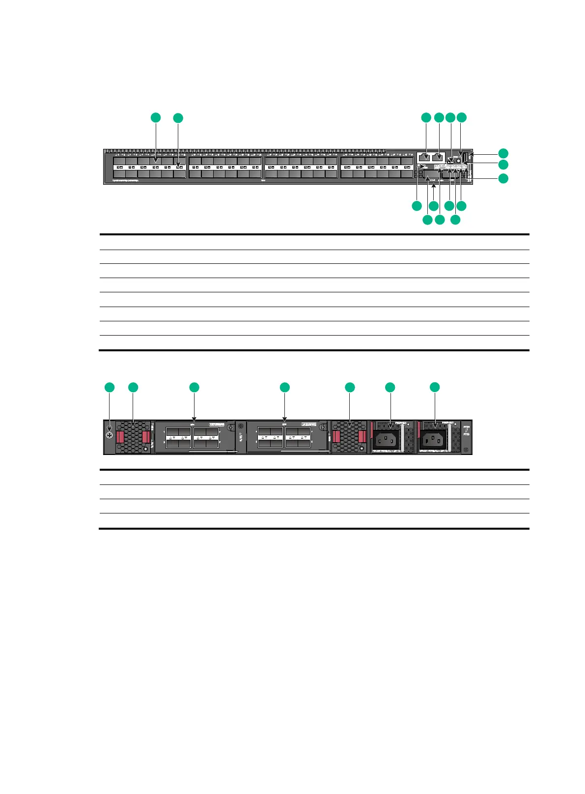
S6520X-54QC-EI & S6520X-54QC-HI
Figure2-3 Front panel
(3) Management Ethernet port
(4) Console port (CONSOLE)
(5) Micro USB console port
(9) System status LED (SYS)
(10) Expansion card 2 status LED (SLOT2)
(11) Expansion card 1 status LED (SLOT1)
(12) Power supply 2 status LED (PWR2)
(13) Power supply 1 status LED (PWR1)
(16) Management Ethernet port LED (ACT/LINK)
Figure2-4 Rear panel
(3) Expansion card 1 (SLOT1)
(4) Expansion card 2 (SLOT2)
(6) Power supply 1 (PWR1)
(7) Power supply 2 (PWR2)
The S6520X-54QC-EI and S6520X-54QC-HI switches come with power supply slot PWR1 empty
and power supply slot PWR2 installed with a filler panel. You can install one or two power supplies for
the switch as required. In Figure2-4, two PSR250-12A1 power supplies are installed in the power
supply slots.
The S6520X-54QC-EI and S6520X-54QC-HI switches come with the two fan tray slots empty. You
must install two fan trays of the same model for the switch. In Figure2-4, two LSWM1FANSCBE fan
trays are installed in the fan tray slots.
The S6520X-54QC-EI and S6520X-54QC-HI switches come with a filler panel in each expansion
slot. You can select expansion cards for the switch as required. In Figure2-4, two LSWM4SP8PM
interface modules are installed in the expansion slots.
 Loading...


