EasyManua.ls Logo

hager SP 015 User Manual

hager SP 015
2 pages
To Next Page IconTo Next Page
Page #1 background imageLoading...
Page #1 background image
SP 015
SP 015
SP 215
Un
Uc (L,N/Q)
Isn (8/20) µs
Ismax (8/20) µs
T °C
Up (L,N/Q)
IP
230 VM
275 VM
15 kA
40 kA
-20 / +60 °C
20
1500 V
Norm
Klasse
DIN VDE 0675
Teil 6 Ent. (11.89)
C
max
125 A gl
Isn = 15 kA (8/20) µs
Ismax = 40 kA (8/20) µs
SP 015
SP 117
6S 5018.b
SP 015
DEFECT
DEFECT
Bedienungsanleitung
User instructions
Notice d’instructions
Bruksanvisning
SP 015, SP 115, SP 215,
SP 315, SP 415, SP 117
SP 015
SP 015
SP 015
SP 015
SP 415
Überspannungsableiter
Overvoltage protection device
Limiteur de surtensions
Överspänningsskydd
D
F
S
GB
L,N, Q mini
16 mm
2
25 mm
2
6 mm
2
L,N, Q maxi
6 mm
2
mini
1,5 mm
2
1,5 mm
2
0,14 mm
2
maxi
0,14 mm
2
I mini : 0,2 A / 12 V DC
I maxi : 1 A / 230 V DC
Hilfsschalter / Contact auxiliaire
Auxiliary contact / Hjälpkontakt
12
14
11
SP 215
SP 015
SP 015
SP 015
SP 315
SP 015
SP 015
SP 015
SP 015
SP 415
SP 315
SP 115
SP 415
SP 117
1 Ph
SP 115
1 Ph + N
SP 215
3 Ph
SP 315
3 Ph + N
SP 415
1 Ph
SP 117
230 VM (50/60 Hz)
Isn : 15 kA (8/20)
Up : 1,5 kV
Uc : 275 V
M
C
SP 015
Question and Answer IconNeed help?

Do you have a question about the hager SP 015 and is the answer not in the manual?

hager SP 015 Specifications

General IconGeneral
Number of Poles1
Tripping CharacteristicC
Rated Voltage230 V
Breaking Capacity6 kA
Poles1P
StandardsIEC 60898-1

Summary

Product Range and Specifications

Product Models and Configurations

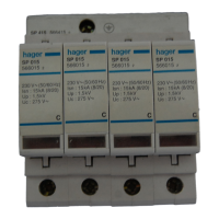
Lists available Hager surge arrester models (SP 015, SP 115, SP 215, SP 315, SP 415, SP 117) and their electrical configurations (1 Ph, 1 Ph + N, 3 Ph, 3 Ph + N).

Technical Data Overview

Details key technical specifications including norm, class, nominal voltage (Un), continuous operating voltage (Uc), voltage protection level (Up), nominal discharge current (Isn), and maximum discharge current (Ismax).

Auxiliary Contact Functionality

Describes the specifications for the auxiliary contact, including minimum and maximum current and voltage ratings for signaling purposes.

Terminal Connection Sizes

Specifies the minimum and maximum conductor cross-sectional areas (mm²) for L, N, and PE connections on the surge arresters.

Installation and Safety Guidelines

Wiring Diagrams for TN Systems

Illustrates recommended wiring configurations for surge arresters in TN-C (3 Ph + PEN) and TN-S (3 Ph + N + PE) earthing systems.

Fuse Recommendations

Provides guidance on appropriate fuse ratings (F1, F2) for protecting the surge arrester and associated circuits.

Grounding Requirements

Emphasizes the importance of grounding surge arresters via the shortest possible route with a minimum conductor cross-section of 6 mm².

Related product manuals