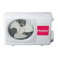
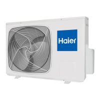
Do you have a question about the Haier 1UH125P1ERG and is the answer not in the manual?
Illustrates the electrical connections for the indoor unit's main control board and components.
Covers safety precautions, selection of installation place, ceiling height, and suspending bolt installation.
Shows the electrical schematic for the indoor unit's main control board and connected components.
Details safety precautions, power supply, interconnecting wires, and installation steps.
Illustrates the electrical connections for the high ESP duct indoor units.
Covers safety precautions, electrical wiring, and installation procedures for high ESP duct units.
Illustrates the refrigerant flow path and key components within the outdoor unit.
Shows the electrical connections and circuit layout for the outdoor unit's control board.
Covers safety, precautions, installation site selection, foundation work, and pipe sizing.
Explains the function and settings of DIP switches on indoor unit PCBs for various configurations.
Lists error codes, malfunction contents, possible reasons, and LED indicators for troubleshooting.
Guides on how to access and interpret parameters and error codes using the digital display and buttons.
| Compressor Type | Rotary |
|---|---|
| Energy Efficiency Ratio (EER) | 3.5 |
| Power Consumption (Cooling) | 1050 W |
| Power Consumption (Heating) | 1100 W |
| Outdoor Unit Weight | 30 kg |
| Power Supply | 230V, 50Hz |
| Outdoor Unit Dimensions (WxHxD) | 780x540x240 mm |


