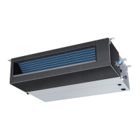
Air outlet
Air inlet
Compressor (inside)
Fig.1 Indoor Unit
1 Operating Control Panel (Fig.2)
2 Emergency switch
3 Remote Control Signal Receiver
4 Power Indicator Lamp (Red)
5 OPERATION Indicator Lamp (Green)
6 TIMER Indicator Lamp (Yellow)
4
5 6
2
3
POWER OPER
TIMER
EMER
Fig.3
AC28NACBEA
PARTS AND FUNCTIONS
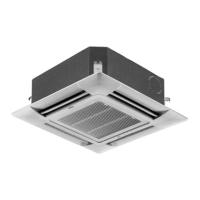
Air outlet
Air inlet
Duct
AU242AHBEA AU28NAHBEA
1
AD242AMBEA AD28NAMBEA
Fig.1 Indoor Unit
1
4
6
7
3
Fig.2
POWER
OPER
TIMER
COMP
EMER
2
1 Operating Control Panel (Fig.2)
2 Emergency switch
3 Remote Control Signal Receiver
4 Power Indicator Lamp (Red)
5 OPERATION Indicator Lamp (Green)
6 TIMER Indicator Lamp (Yellow)
7 Compressor Run Lamp (Green)
8 Intake Grill (Fig.3)
9 Air Filter
10
UP/DOWN Air Direction Flaps
11
RIGHT/LEFT Air Direction Louvers
(behind UP/DOWN Air Direction Flaps)
3
9
8
Fig.1
1110
5
AC242ACBEA