Do you have a question about the Haier AB28NACBEA and is the answer not in the manual?
Explains the coding system for product models and their components.
Details the coding logic for outdoor and indoor unit models.
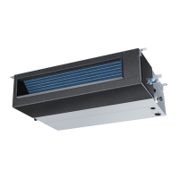
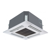
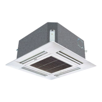
Introduces different series like Convertible and Duct types.
Critical safety information and warnings for installation and operation.
Important safety precautions and warnings for installation and operation.
Provides detailed drawings of indoor unit dimensions for specific models.
Shows dimensional drawings for AD242AMBEA and AD28NAMBEA indoor units.
Presents dimensional drawings for the AD242AHBEA indoor unit.
Displays dimensional drawings for the AC242ACBEA indoor unit.
Provides dimensional drawings for the AC28NACBEA indoor unit.
Shows dimensional drawings for AU242AHBEA, AU28NAHBEA, AU282AHBEA outdoor units.
Lists required tools for the installation process.
Lists standard accessories included with the unit.
Details installation steps and important considerations.
Identifies and explains the components and functions of the unit.
Illustrates the components of the indoor unit with labels.
Details the functions and operations of the remote controller.
Sets the desired temperature for the air conditioner.
Controls the airflow direction swing function.
Starts and stops the air conditioner unit.
Selects the operating mode (Auto, Cool, Dry, Heat, Fan).
Activates the health mode, potentially with ion functions.
Sets the correct time for the remote controller.
Controls the filter status or function.
Selects the unit code (A or B).
Resets the remote controller to its correct operation.
Locks the remote controller buttons to prevent accidental changes.
Activates the control panel light.
Adjusts settings like timer and clock.
Selects High or Soft operation modes.
Confirms TIMER and CLOCK settings.
Activates the fresh air intake function.
Sets the air conditioner to sleep mode for comfort.
Selects the fan speed (Low, Mid, High, Auto).
Procedure for setting the clock on the remote controller.
Instructions for loading and replacing batteries in the remote controller.
Illustrates the refrigerant flow during cooling and heating operations.
Flow chart detailing the unit's power on/off sequence.
Flow chart illustrating the cooling operation logic.
Flow chart explaining the dehumidifying operation logic.
Flow chart describing the heating operation logic.
Lists failure codes for remote and wired control units with descriptions.
Provides detailed malfunction flow charts for cooling and heating issues.
Wiring diagrams for various unit types.
Wiring diagrams for single-phase and three-phase outdoor units.
Wiring diagrams for various indoor unit types.
Exploded view diagram for outdoor units (24/28 series).
Exploded views and parts lists for various indoor unit models.
Performance curves related to cooling capacity based on air conditions.
Performance curves related to heating capacity based on air conditions.
Performance graphs (Cool Capacity, EER) for AD28NAMBEA model.
Performance graphs (Cool Capacity, EER) for AC28NACBEA model.
Performance graphs (Cool Capacity, EER) for AB28NACBEA model.
Presents charts detailing the noise levels of the air conditioning units.
Air velocity and temperature distribution charts for AC28NACBEA.
Air velocity and temperature distribution charts for AB28NACBEA.
Air velocity and temperature distribution charts for AD28NAMBEA.
| Brand | Haier |
|---|---|
| Model | AB28NACBEA |
| Category | Air Conditioner |
| Language | English |