13
Troubleshooting
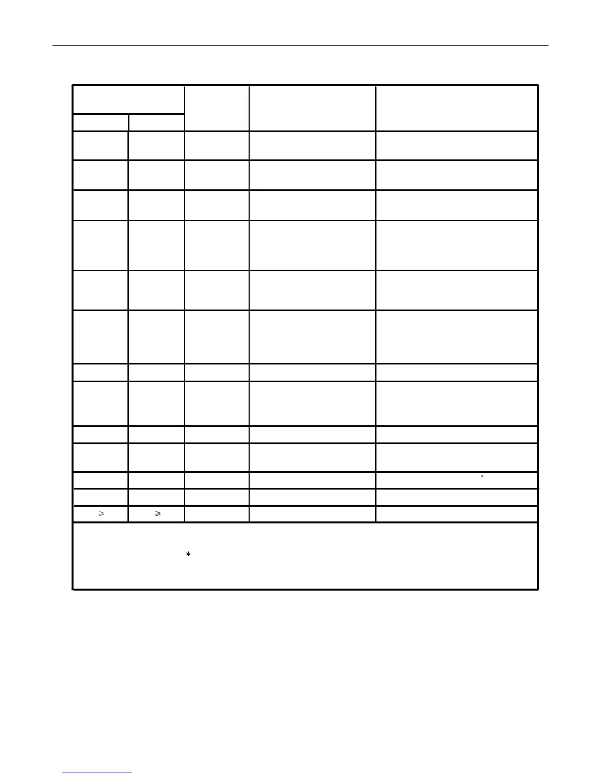
INDOOR UNIT TROUBLE SHOOTING
Malfunction of indoor unit
ambient temperature sensor
LED flash times
of indoor PCB
Wired
controller
display
LED4 LED3
Contents of Malfunction Possible reasons
0 1 01
Sensor disconected,or broken, or at
wrong position,or short circuit
0 2 02
Malfunction of indoor unit
piping temperature sensor
Sensor disconected,or broken,or at
wrong position,or short circuit
0
4 04
EEPROM wrong of indoor
PCB
EEPROM chip disconected or broken
or wrong programmed, or PCB broken
0 7 07
Abnormal communication
between indoor and outdoor
units
Wrong connection,or the wires be
disconected or wrong address setting
of indoor unit or faulty power supply
or PCB hardware malfunction
0 8 /
Abnormal communication
between wired controller and
indoor unit
Wrong connection or wired controller
broken,or PCB hardware malfunction
0 12 0C
Malfunction of drain system
Pump motor disconnected or at wrong
p o s i t i o n , or t h e f l o a t s witc h
disconnected, or at wrong position,or
the short circuit bridge disconnected
0 13 0D
Zero cross signal wrong
Zero cross signal detected wrong
0 14 0E
Abnormal communication
between main control PCB &
fan motor driver
communication wire disconnected or
wrong connected or PCB hardware
malfunction
0 15 0F
Fan motor overcurrent
Fan motor current too high
0 17 11
DC voltage high or low
DC voltage of the fan motor driver too
high or too low
0 18 12
F.M.D temperature high Fan motor driver over 95 C
0 19 13
Fan motor out of step
Wrong rotor location detected
M( 1) N( 0)
/
Error of the outdoor unit
See note 1,2
Note:
1.The outdoor failure can also be indicated by the indoor unit,the checking method as follows:
outdoor unit error code=(M 10+N)-20.LED4 flash M times and LED3 flash N times .
2.To get much more details about the out door unit failure,please refer to the outdoor unit trouble shooting list.
 Loading...