Do you have a question about the Haier AD28NAMBEA and is the answer not in the manual?
Lists key features of the air conditioning units including auto-restart, group control, auto-changeover, and refrigerant type.
Explains the coding system for United Outdoor Unit models, detailing capacity, type, voltage, and features.
Explains the coding system for Indoor Cassette type units, detailing capacity, type, voltage, and features.
Details the standard operating conditions for nominal cooling and heating based on temperature and humidity.
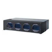
Introduces the Convertible Type series, highlighting features like flexible installation and dual air outlet design.
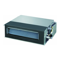
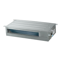
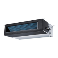
Introduces the Duct Type series, focusing on concealed machine body and flexible installation.
Describes the characteristics of Cassette Type units, including invisible body, healthy filter, and easy installation.
Details the operating temperature ranges for different climate types (T1, T2, T3) for cool only and heat pump units.
Comprehensive table detailing specifications like capacity, power, current, noise, and dimensions for various models.
Details specifications for the AP242ACBEA model, including function, capacity, power, and dimensions.
Details specifications for the AU28NAHBEA model, including function, capacity, power, and dimensions.
Details specifications for the AU282AHBEA model, including function, capacity, power, and dimensions.
Details specifications for the AD28NAMBEA model, including function, capacity, power, and dimensions.
Details specifications for the AC28NACBEA model, including function, capacity, power, and dimensions.
Details specifications for the AB28NACBEA model, including function, capacity, power, and dimensions.
Covers critical safety advice for installation and operation, including warnings about injury and property damage.
Provides detailed safety instructions on grounding, earth leakage breakers, and handling combustible gas.
Illustrates physical dimensions of various indoor unit models including cassette and duct types.
Displays additional diagrams for AD242AHBEA and AC242ACBEA indoor unit dimensions.
Illustrates physical dimensions of outdoor unit models like AC28NACBEA and AU series.
Lists necessary tools and standard accessories required for the installation process.
Outlines the order of installation work and highlights important safety considerations.
Details criteria for selecting a suitable installation place for outdoor units, considering air circulation and wind.
Covers the steps for installing the outdoor unit, including foundation and fixing methods.
Covers piping size, limitations for length and height, and precautions for refrigerant piping.
Details selection of wire sizes, circuit protection, and precautions for electric wiring.
Reiterates site selection criteria for outdoor units, focusing on open space and wind direction.
Details piping dimensions, length limits, and connection methods, including fastening torque.
Describes the air discharging method using nitrogen and procedures for checking gas leakage.
Covers vacuumizing the indoor unit and calculating additional refrigerant charging amounts.
Provides critical warnings and important notes for the entire installation process, including electrical safety.
Details pipe selection, connection methods, welding, and checks after installation.
Covers initial steps for indoor unit installation, including tools, accessories, and basic preparation.
Describes ceiling height requirements, suspending bolt positioning, and opening preparation.
Details cutting ceiling openings, installing suspending bolts, and connecting pipes before mounting.
Covers indoor unit installation steps for new and existing ceilings and refrigerant piping connections.
Details connecting refrigerant pipes, torque specifications, and pipe insulation.
Covers installation of drainage pipes, including slope, insulation, and cautions.
Details wiring practices, connection rules, and examples for indoor unit electrical wiring.
Describes the process of installing the ornament panel, including handling and precautions.
Covers installing the ornament panel on the indoor unit and its associated wiring.
Addresses considerations for mounting the unit on high ceilings and installing pads.
Details the installation of the inlet grill and cover plate onto the ornament panel.
Outlines the steps for conducting a test run before and after installing the ornament panel.
Explains preparation steps for convertible type units, including selecting ceiling or floor installation.
Covers the overall installation process for convertible units, including preparing the indoor unit and removing the intake grill.
Details the installation steps for convertible units when floor mounting, including piping and drain hose.
Details the installation steps for convertible units when under-ceiling mounting, including drilling and piping.
Covers installing the indoor unit, drilling anchor bolt holes, and mounting brackets.
Details the installation of the drain hose for convertible units, including insulation and routing.
Focuses on accessing and working with the indoor unit's electrical component box for wiring.
Provides final wiring steps for the indoor unit and guidance for the end-user.
Covers unit preparation, selecting installation locations, and hanging bolt dimensions.
Details ceiling opening dimensions, hanger bolt installation, and piping direction considerations.
Covers installing the indoor unit, adjusting its levelness, blower unit tap selection, and drain piping.
Explains blower unit tap settings and drain piping for duct types, including good and improper piping.
Details drain piping for multiple units and conducting drainage tests after electrical work.
Explains calculating air duct dimensions based on resistance and provides charts for simple ducts.
Covers attentive matters and examples of improper installation for air suction and discharging ducts.
Covers selecting the installation location for High ESP Duct units, ensuring airflow and space.
Details positioning hoisting screws and preparing the ceiling for unit installation.
Covers the process of installing hanger bolts for High ESP Duct units.
Covers installing the indoor unit, adjusting its levelness, and drain piping.
Details drain piping guidelines, including downhill grade and avoiding traps.
Covers multi-unit drain piping and drainage tests for High ESP Duct units.
Explains how to operate the fan controller in the electric box and select the appropriate capacity.
Details refrigerant pipe connection, torque specifications, and heat insulation requirements.
Identifies parts of the indoor unit for cassette type, including air filter, outlet, and drain hose.
Identifies parts for different indoor and outdoor unit types, including control panels and motors.
Explains the function of each button on the remote controller for mode, temp, swing, and power.
Covers display indicators, battery loading, confirmation indicators, and operational notes.
Explains how to start, select modes, adjust fan speed, and stop the unit using the remote.
Provides detailed explanations for AUTO, COOL, HEAT, and DRY modes, including temperature settings.
Explains how to adjust airflow direction (up/down, left/right) using the SWING button.
Explains how to use the sleep function in COOL, DRY, and HEAT modes for comfortable sleep.
Guides through setting and canceling timer functions, including mode selection and time adjustment.
Explains selecting and confirming timer modes (ON, OFF, ON-OFF) and setting times.
Describes the filter up/down function for the AB182ACBEA model, including activation and cancellation.
Explains the operation and notices for the High Mode, suitable for rapid temperature achievement.
Explains the operation and notices for the Soft Mode, suitable for silent operation.
Describes how to set and cancel the auto restart function after a power failure.
Identifies buttons and their basic functions on the wired controller, including mode, fan, and temp.
Details button functions and explains display descriptions for various modes and settings.
Explains fan operation modes (HIGH, MED, LOW, FIX) and display indicators on the wired controller.
Covers AUTO, COOL, HEAT, DRY modes and timer setup procedures for the wired controller.
Explains timer cancellation, filter functions, and elevating filter for wired controllers.
Details the demand operation function, allowing nominal mode setting for multiple units.
Describes central control limitations and ventilation modes (AUTO, RECOVERY, NORMAL).
Covers querying and clearing malfunction history and indoor performance states.
Explains how to change function switches for various settings like controller type and temperature compensation.
Details wiring requests and address settings for connecting indoor units to a central controller.
Provides continued address settings for central control, listing DIP switch configurations.
Provides continued address settings for central control, listing DIP switch configurations.
Provides continued address settings for central control, listing DIP switch configurations.
Compares functions available on master and slave wired controllers, highlighting differences.
Explains different wiring connection methods for wired controllers and indoor units.
Details communication wiring specifications, length requirements, and wire dimensions.
Illustrates the refrigerant flow path during cooling and heating operations within the system.
Flowchart detailing the logic for turning the air conditioning unit on/off and handling troubles.
Flowchart detailing the logic for cooling operation, including swing, fan speed, and thermostat control.
Flowchart detailing the logic for dehumidifying operation, including swing, fan speed, and temperature.
Flowchart detailing the logic for heating operation, including swing, defrosting, and fan speed.
Lists failure codes indicated by indoor running lamp flash times for remote control units.
Lists failure codes (E1-E9, E0) displayed on the wired controller for various malfunctions.
Flowchart for diagnosing cooling malfunctions, covering TEMP, load, valve, compressor, and filter issues.
Flowchart for diagnosing heating malfunctions, covering TEMP, load, valve, compressor, and cold air issues.
Troubleshooting steps for a wired controller with no display or failure to operate.
Troubleshooting steps for E0 alarm, indicating a malfunction of the indoor unit's floater switch.
Troubleshooting steps for E1 alarm, indicating an abnormal indoor ambient temperature sensor.
Troubleshooting steps for E2 alarm, indicating an abnormal indoor piping temperature sensor.
Troubleshooting steps for E8 alarm, indicating communication malfunction between control panel and indoor units.
Provides wiring diagrams for single-phase and three-phase outdoor units.
Provides wiring diagrams for various indoor unit types: convertible, cassette, and duct.
Wiring diagram specifically for Mid ESP Duct type indoor units.
Wiring diagram specifically for High ESP Duct type indoor units.
Wiring diagram for cabinet units, detailing connections for various components.
Detailed circuit diagram for PCB 0010451167, showing component connections and layout.
Shows component layout on the PCB from a horizontal perspective.
Shows component layout on the PCB from a vertical perspective.
Lists operating conditions for the PCB, including temperature, humidity, and power supply.
Details the purpose and connection for each port on the PCB.
Continues the detailed definition of PCB ports and their functions.
Explains how to select PCB functions using DIP switches SW1 through SW5.
Details selecting control types (remote, wired, central) and wiring requests.
Explains the status indicated by LEDs on the indoor PCB for remote receiver and communication.
Exploded view diagram showing the components of outdoor units (24/28 series).
List of spare parts for outdoor units (24/28 series), including part numbers and failure rates.
List of spare parts for AU28NAHBEA model, including part numbers and failure rates.
List of spare parts for AU282AHBEA model, including part numbers and failure rates.
Exploded view diagram of the AC242ACBEA indoor unit.
List of spare parts for AC242ACBEA indoor unit, including part numbers and failure rates.
Exploded view diagram of the AC28NACBEA indoor unit.
List of spare parts for AC28NACBEA indoor unit, including part numbers and failure rates.
Exploded view diagrams for AD242AMBEA and AD28NAMBEA indoor units.
List of spare parts for AD242AMBEA/AD28NAMBEA indoor units.
Exploded view diagrams for AD242AHBEA and AD28NAHBEA indoor units.
List of spare parts for AD242AHBEA/AD28NAHBEA indoor units.
Exploded view diagrams for cassette type indoor units.
List of spare parts for cassette type indoor units.
Exploded view diagram of the AB28NACBEA indoor unit.
List of spare parts for AB28NACBEA indoor unit.
General exploded view of indoor unit components, showing various parts.
Exploded view diagram of the AP242ACBEA indoor unit.
List of spare parts for AP242ACBEA indoor unit.
Performance curves related to cooling capacity based on indoor air humid ball and outdoor air dry ball.
Performance curves related to heating capacity based on outdoor air humid ball and indoor air dry ball.
Cooling capacity and EER graphs for AD28NAMBEA model at various indoor temperatures.
Heating capacity and COP graphs for AD28NAMBEA model at various outdoor temperatures.
Cooling capacity and EER graphs for AC28NACBEA model at various indoor temperatures.
Cooling capacity and EER graphs for AB28NACBEA model at various indoor temperatures.
Charts detailing the noise levels of the air conditioning units.
Air velocity and temperature distribution charts for AC28NACBEA in cooling mode.
Air velocity and temperature distribution charts for AB28NACBEA in cooling mode.
Air velocity and temperature distribution charts for AD28NAMBEA in cooling mode.
| Cooling Capacity | 2.8 kW |
|---|---|
| Heating Capacity | 3.2 kW |
| Power Supply | 220-240V, 50Hz |
| Energy Efficiency Ratio (Cooling) | 3.21 |
| Energy Efficiency Ratio (Heating) | 3.61 |
| Refrigerant | R410A |
| Net Weight (Outdoor Unit) | 25 kg |
| Noise Level (Outdoor) | 50 dB(A) |