

R
Renee ValdezSep 1, 2025
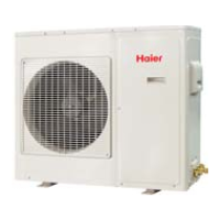
What to do if my Haier AU282XHERA compressor vibration is too big?
- AacooperSep 1, 2025
If your Haier Air Conditioner's compressor vibration is too big, this indicates a faulty compressor. The suggested solution is to inspect and replace the faulty compressor.